





By Felix Lee | CEO at Forgecise Published: August 6, 2026
Executive Summary (TL;DR) > Laser formation is the core physical process of metal 3D printing, especially Selective Laser Melting (SLM). To build dense, low-stress parts, engineers must balance energy input, control liquid melt pools, and manage thermal strain. This guide covers basic physics, key defect causes, material rules, real-time sensors, and aerospace standards like AS9102.
Table of Contents
1. How Lasers Form Metal Parts: SLM vs. EBM
Quick Answer > Selective Laser Melting (SLM) uses a bright laser beam to fully melt metal powder layer by layer under protective argon gas. Electron Beam Melting (EBM) uses an electron beam inside a hot vacuum. SLM makes finer details, while EBM keeps thermal strain lower.
+-----------------------------------------------------------------------+
|                       METAL 3D PRINTING PROCESS                       |
+-----------------------------------+-----------------------------------+
|     Selective Laser Melting       |      Electron Beam Melting        |
|               (SLM)               |               (EBM)               |
+-----------------------------------+-----------------------------------+
| • 1070 nm Fiber Laser (200-1000W) | • High-Energy Electron Beam       |
| • Argon Gas (O2 < 0.1%)           | • High Vacuum Environment         |
| • Rapid Melt & Solidification     | • Powder Preheated Near β-Transus |
| • Layer Thickness: 20–60 μm       | • Lower Thermal Stress            |
| • High Surface Resolution         | • Lower Resolution / Rougher      |
+-----------------------------------+-----------------------------------+
Selective Laser Melting (SLM)
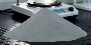
SLM (also called Laser Powder Bed Fusion) relies on a high-power fiber laser. This beam has a wavelength of 1070 nm and runs between 200 W and 1000 W. The laser sweeps across thin powder beds (20 μm to 60 μm thick) to melt shapes layer by layer.
Unlike Selective Laser Sintering (SLS), which only glues grains together, SLM melts metal powder completely. The liquid metal cools into solid, fully dense parts. To keep hot reactive metals from catching fire or rusting, SLM works inside a sealed chamber filled with argon gas. Operators keep oxygen levels below 0.1% (and below 0.05% for sensitive metals like titanium).
Electron Beam Melting (EBM)
EBM trades light photons for an electron beam. The build happens inside a tight vacuum. The machine preheats the powder bed to high temperatures near the alloy’s $\beta$-transus phase point.
Because the entire bed stays hot throughout the build, EBM parts suffer far less internal heat strain. This makes EBM great for thick titanium aerospace brackets. However, EBM parts have rougher surfaces and lower visual detail than SLM parts.
2. Energy Density and Process Parameters
Quick Answer > Volumetric Energy Density (VED) measures how much laser energy hits a cubic millimeter of powder. Too little energy leaves raw, unmelted powder pockets. Too much energy drills hot holes that trap gas bubbles.
The Energy Density Formula
Engineers use the Volumetric Energy Density ($ED$) equation to track laser heat input in Joules per cubic millimeter ($\text{J/mm}^3$):$$ED = \frac{P}{v \cdot h \cdot t}$$
Where:
- $P$ = Laser Power (Watts, $\text{W}$)
- $v$ = Scanning Speed (Millimeters per second, $\text{mm/s}$)
- $h$ = Hatch Distance between scan lines (Millimeters, $\text{mm}$)
- $t$ = Powder Layer Thickness (Millimeters, $\text{mm}$)
ENERGY DENSITY SPECTRUM
--------------------------------------------------------------------------------
[ UNDER-MELTING ] ---------> [ OPTIMAL WINDOW ] ---------> [ OVER-MELTING ]
• Low Energy                 • Balanced Input              • High Energy
• Lack of Fusion (LOF)       • High Density                • Keyhole Porosity
• Balling Effect             • Strong Bonding              • Heavy Spatter
• Interlayer Porosity        • Low Defects                 • Element Burn-off
--------------------------------------------------------------------------------
Finding the Right Balance
Every metal alloy needs a specific range of laser energy:
- Under-Melting (Low Energy): The laser cannot melt the powder all the way through. This creates Lack of Fusion (LOF) gaps and balling, where liquid metal beads up like water drops on glass.
- Over-Melting (High Energy): The laser vaporizes metal, digging a deep hole called a keyhole. When this hot vapor cavity collapses, it traps argon gas as round pores. It also causes heavy spatter and burns away light alloying elements.
Benchmark Ranges
- Titanium (Ti-6Al-4V / TC4): ~60–90 $\text{J/mm}^3$
- Inconel 718 (IN718): ~50–80 $\text{J/mm}^3$
- Aluminum Alloys: Need much higher laser power and slower speeds because bright aluminum reflects laser light and pulls heat away fast.
Engineers must use Design of Experiments (DOE) tests, cut sample cross-sections, and run CT scans to build custom parameter cards for each metal batch.
3. Melt Pool Physics and 4 Main Defects
Quick Answer > As the laser touches metal powder, it forms a small pool of liquid metal. Temperature differences pull liquid around in currents (Marangoni convection). Poor fluid balance creates four defects: Lack of Fusion, Gas Porosity, Balling, and Cracking.
       [ Laser Beam ]
             |
             v
   ~~~~~~~~~~~~~~  <-- Protective Gas Flow
  /  Melt Pool   \
 ( Marangoni Flow ) <-- Surface Tension Gradient
  \~~~~~~~~~~~~~~/
  [ Solid Metal ]
The 4 Main Defects
- Lack of Fusion (LOF):
- Cause: Low laser power, fast speeds, or overly thick powder beds leave raw powder between layers.
- Impact: Sharp, unbonded gaps weaken the part. LOF is the main reason metal 3D printed parts snap under repeated loads.
- Gas Porosity:
- Cause: Collapsed keyholes trap chamber gas, or damp powder releases moisture bubbles into the melt pool.
- Impact: Small round holes reduce ultimate tensile strength.
- Balling:
- Cause: Surface tension pulls high-speed liquid tracks into tiny round spheres instead of smooth lines.
- Impact: Rough top surfaces hit and damage the powder wiper blade.
- Cracking:
- Cause: Hot Cracking happens when liquid films tear during cooling. Solid-State Thermal Cracking happens when cold metal shrinks violently.
- Impact: Common in nickel superalloys (IN718), high-strength aluminum, and tool steels.
Fixing these defects requires matching energy settings, preheating build plates, using smart laser paths, and keeping argon gas pure.
4. Scan Patterns and Thermal Control
Quick Answer > Scan paths steer how the laser travels across the powder bed. Breaking large areas into small islands and turning laser path angles by 67° on every layer spreads heat evenly and stops parts from bending.
LAYER N                     LAYER N+1 (Rotated by 67°)
+---+---+---+               +---+---+---+
|///|\\\|///|               |==/|--/|==/|
+---+---+---+   ------>     +---+---+---+
|\\\|///|\\\|               |--/|==/|--/|
+---+---+---+               +---+---+---+
 (Island Pattern)            (Golden Angle Disruption)
Island Patterns
Sweeping a laser across a wide plate in one direction creates huge heat differences. Instead, software breaks layers into small Islands or Strips (often $5\text{ mm} \times 5\text{ mm}$). The laser jumps between separate squares to keep heat balanced.
The 67° Rotation Rule
On every new layer, the software turns the laser travel direction by 67° (the Golden Angle). This rotation stops scan paths from stacking on top of each other. It scatters heat build-up and lowers directional stress differences.
Extra Path Options
- Contour Lines: The laser traces outer part edges separately to leave smooth walls and sharp corners.
- Hatch Overlap: Adjacent scan tracks must overlap by 30% to 50% of the laser spot size so paths fuse together completely.
- Adaptive Scanning: Modern machine tools alter laser power and travel speed on the fly when passing over thin walls or sharp spikes.
5. Heat Strain and Part Warping
Quick Answer > Metal 3D printing causes extreme heat changes up to10^6\text{ K/m}(one million Kelvin per meter). As new top layers shrink against cold bottom metal, internal thermal strain pulls parts out of shape.
       [ Cool Surface Layer Shrinks ]
                   ||
                   \/
   ====================================  <-- Extreme Residual Strain
   ------------------------------------
       [ Hot Underlying Structure ]
                   ||
                   \/
 [ Baseplate Warping / Part Separation ]
How Heat Strain Bends Parts
Because metal melts and freezes in microseconds, temperature changes inside the bed reach 10^6\text{ K/m}. Fresh top layers try to shrink as they cool, but the cold metal underneath holds them still. This pulls the metal tight, locking in heat strain.
Unchecked heat strain leads to three failure points:
- Baseplates bowing upward at the corners.
- Parts snapping off their support pins mid-print.
- Cracks opening up inside thick metal walls.
Ways to Stop Strain
- Preheat Baseplates: Heating the print plate narrows the temperature gap (\Delta T) between liquid metal tracks and solid metal.
- Symmetric Scan Paths: Laser paths that work outward from the middle keep internal pull forces balanced.
- Strong Supports: Heavy support geometries lock parts firmly down to the heavy steel build plate.
- Stress-Relief Ovens: Heating printed parts while they remain attached to the plate unlocks frozen internal stress before operators cut them off.
Warning: Crack-prone metals like IN718 nickel, high-strength aluminum, and tool steel require heated build plates. Without preheating, these parts will break midway through a job.
6. Multi-Laser Systems and Stitching Lines
Quick Answer > Production 3D printers use 2 to 12 lasers working side by side to finish jobs faster. The overlap lines where laser work zones touch are called “stitching lines.” Operators must calibrate these seams carefully to avoid weak joints and micro-cracks.
[ Laser A Zone ]  ===>  | STITCHING LINE |  <===  [ Laser B Zone ]
                        | (Energy Overlap) |
                        | Micro-crack Risk |
The Stitching Problem
To build large metal parts quickly, modern machines split powder beds among several laser heads. Where laser work zones meet, heat can stack up or drop off.
Poor laser alignment creates three risks along stitching seams:
- Weak spots that fail early under repeated load tests.
- Tiny steps or height offsets on outer part skins.
- Micro-cracks caused by overlapping heat spots.
Fixing Laser Seams
- Power Calibration: Match optics and power output so every laser fires with equal brightness.
- Overlap Settings: Use gentle, lower-power scan settings right on boundary seams.
- Keep Seams Away From Stress: Position stitching lines away from thin, highly stressed part sections.
- Boundary Checks: Test density and strength on samples cut directly across stitching seams.
7. Material Rules: Titanium, Nickel, Aluminum, and Steel
Quick Answer > Different metal powders need different printing rules. Titanium demands pure argon gas, Nickel needs hot preheating, Aluminum needs high laser energy, and Stainless Steel prints easily across broad settings.
| Material | Primary Engineering Risk | Key Processing Rule | Post-Processing Need |
|---|---|---|---|
| Titanium (Ti-6Al-4V / TC4) | Takes in oxygen fast; forms brittle \alpha’ martensite phase. | Keep chamber O_2 < 0.05\%; protect powder from air. | Mandatory heat treatment to restore metal toughness. |
| Nickel Alloy (Inconel 718) | Prone to hot cracks as liquid metal freezes. | Use high build plate heat; use low-strain scan paths. | Solution and aging heat treatments in vacuum ovens. |
| Aluminum Alloys (AlSi10Mg) | Reflects laser light, loses heat fast, holds gas pores. | Use high laser power, slow speeds, dry powder, pure gas. | Stress relief heat treatment. |
| Stainless Steel (316L) | Easy to print; risks surface rust if gas purity drops. | Use standard hatch overlaps and clean gas flow. | Optional heat treatment; easy support removal. |
Never copy settings from one metal to another. Every alloy needs its own tested settings card.
8. Real-Time Sensors and Quality Monitoring
Quick Answer > In-situ monitoring uses cameras and light sensors to watch melt pools while printers run. These sensors catch spatter spikes and melting errors early, turning 3D printers into smart tools.
[ High-Speed Camera / Photodiode ]
              |
              v (Real-time Melt Pool Signal)
     [ Machine Learning ]
              |
     +--------+--------+
     |                 |
     v                 v
[ Live Parameter ]  [ Instant Alarm / ]
[ Adjustment    ]  [ Print Abort     ]
Sensor Types
- High-Speed Cameras: Mounted over or inside laser paths to track melt pool size, spatter drops, and metal vapor clouds.
- Photodiodes: Read light brightness and heat changes directly from the liquid melt spot.
- Acoustic & Heat Sensors: Listen for micro-cracks and map temperature maps across the build bed.
Live Corrections
These sensors build a digital “process fingerprint.” Computer algorithms read these signals live. When errors pop up—like bad spatter or unmelted powder—the software alerts operators or adjusts laser settings instantly to save the print.
After prints finish, technicians run Industrial CT Scans (X-ray inspection) on critical parts to find hidden internal pores without cutting parts open.
9. Operator Checklist for Print Runs
Quick Answer > Consistent metal printing relies on good machine habits. Operators should track chamber gas, laser health, and wiper blades during builds, then run NDT tests on finished parts.
Mid-Print Checklist
- [ ] Oxygen Levels: Confirm chamber O_2 stays under limits (<0.1\%, or <0.05\% for titanium).
- [ ] Laser Output: Watch for laser lens contamination or power drops.
- [ ] Wiper Blade: Look for blade jumps, blade wear, or bumps against raised parts.
- [ ] Spatter Alarms: Clean glass optical windows if spatter increases.
- [ ] Powder Layers: Make sure fresh powder spreads evenly across the entire plate.
Post-Print Steps
- Visual Inspection: Check parts for curled edges, rough surfaces, or plate lifting.
- Non-Destructive Testing (NDT): Run dye penetrant checks, X-rays, or Industrial CT scans.
- Lab Coupon Checks: Cut test bars off the plate to measure tensile strength and inspect metal grains under microscopes.
Log every machine error immediately. Metal 3D printing requires active control over raw physics on every layer.
10. Process Qualification and AS9102 Standards
Quick Answer > Industrial production locks tested parameters into a locked setup package. Any new machine, material batch, or setting change must pass qualification tests, including AS9102 First Article Inspection (FAI).
[ DOE Parameter Testing ] ---> [ Sample Testing (CT/Tensile) ]
                                          |
                                          v
[ Freeze Parameter Package ] <--- [ AS9102 FAI Approval ]
              |
              v
[ Mass Production + Cpk Statistical Control ]
Qualification Steps
- Triggers: Bringing in a new printer model, new powder supplier, or altered speed setting requires a full qualification check.
- Coupon Testing: Print sample bars, density cubes, and pins across all plate corners to measure real strength and part density.
- Lock Parameters: Save approved machine setups into a Qualified Parameter Package. Machine operators cannot alter locked settings without a re-test.
Industrial Standards
- AS9102 First Article Inspection (FAI): Aerospace rules require paperwork proving that the first finished part matches all CAD shapes, material properties, and surface limits.
- Process Capability Index (C_{pk}): Tracks statistical proof that part quality stays identical across long print runs and repeated powder reuse cycles.
11. Practical Troubleshooting Matrix
Quick Answer > Use a standard symptom-cause chart to fix metal printing errors quickly and cut machine downtime.
| Problem / Symptom | Root Cause | Fix Action |
|---|---|---|
| Spatter Increases Suddenly | Dirty protection glass, laser power drift, or damp powder. | Clean or replace optical glass; calibrate laser output; bake powder dry. |
| Lack of Fusion (LOF) | Fast scan speeds or low laser power for the chosen layer thickness. | Slow down scan speed (v) or increase laser power (P) to raise energy density (ED). |
| Internal Gas Pores | Keyhole collapse from high energy, or gas trapped inside raw powder. | Lower energy density; check chamber seals for air leaks; use degassed powder. |
| Baseplate Warping | High temperature differences (\Delta T) creating strong pull strain. | Turn on or raise baseplate preheating; add thicker support pins. |
| Part Wall Cracks | High internal thermal strain in hard alloys, or poor laser paths. | Raise preheating temperatures; switch to island scan patterns with 67° path turns. |
| Multi-Laser Stitch Lines | Poor laser alignment or uneven power between laser optics. | Recalibrate multi-laser overlapping offsets; align power across all laser heads. |
Save this chart inside your Manufacturing Execution System (MES) software so floor technicians can fix issues fast.
Frequently Asked Questions (FAQ)
What is the main difference between SLM and SLS?
SLM fully melts metal powder into dense solid parts under argon gas. SLS only heats powder grains enough to bond their surfaces without complete melting, which is mostly used for plastics.
How do I calculate laser energy density in metal 3D printing?
Use the Volumetric Energy Density formula: $ED = \frac{P}{v \cdot h \cdot t}$. Multiply scan speed ($v$) by hatch distance ($h$) and layer thickness ($t$), then divide laser power ($P$) by that total.
Why do printers rotate laser scan paths by 67 degrees on each layer?
Rotating scan paths by 67° breaks up directional heat patterns across stacked layers. This stops stress from building along the same lines, reducing part warping.
What causes Lack of Fusion defects in metal prints?
Lack of Fusion happens when laser energy is too low, scan speeds are too fast, or powder layers are too thick. The laser fails to melt powder completely, leaving unbonded gaps between layers.
About the Author
Felix Lee is the CEO at Forgecise, an advanced manufacturing technology firm focused on industrial additive manufacturing process setups, thermal stress analysis, and aerospace qualification workflows.