





Author: Felix Lee, CEO at Forgecise
Last Updated: August 10, 2026
Reviewed by: Forgecise Engineering Team
Table of Contents
Metal 3D Printing Post Processing: CNC Machining, Finishing, and Hybrid Manufacturing Guide
Quick Answer
Metal 3D printing post processing includes machining, finishing, and inspection steps used after printing to achieve final part accuracy, surface quality, and functional performance. CNC milling, turning, drilling, grinding, polishing, and hybrid manufacturing help convert printed metal components into production-ready parts.
TL;DR
- Metal 3D printing creates complex shapes, but printed surfaces and tolerances often need further improvement.
- CNC machining creates accurate holes, mounting surfaces, threads, and precision features.
- Grinding and polishing improve sealing surfaces, friction performance, and internal surface quality.
- Hybrid additive and subtractive manufacturing combines printing and machining in one workflow.
- CMM inspection and digital twin feedback help maintain stable production quality.
Introduction: Why Printing Is Only One Step in Metal Part Production
Metal 3D printing has changed how engineers design components.
It allows manufacturers to create:
- Lightweight structures
- Internal channels
- Topology-optimized parts
- Complex geometries that are difficult to machine from solid material
However, printing alone does not always create a finished engineering part.
A production component may require:
- Tight dimensional tolerance
- Smooth sealing surfaces
- Accurate bearing holes
- Reliable threaded connections
- Controlled surface roughness
These requirements often need additional machining.
Here is the practical reality:
Metal 3D printing creates the shape. CNC machining creates the final function.
At Forgecise, we often see companies new to additive manufacturing expect printing to replace machining completely. In industrial production, the strongest results usually come from combining both technologies.
The printed structure provides design freedom.
Machining provides precision.
Why Do Metal 3D Printed Parts Need Post Processing?
Metal 3D printed parts usually require post processing because the printed condition cannot always meet final production requirements.
During printing, parts may develop:
- Layer marks
- Powder particles
- Balling defects
- Support removal marks
- Thermal distortion
- Residual stress
Typical printed metal parts may have:
- Surface roughness around Ra 6–12 μm
- Dimensional variation around ±0.1 mm
Many industrial applications require much tighter control:
- General precision surfaces: ±0.02 mm
- High accuracy areas: ±0.005 mm
- Surface finish: Ra ≤1.6 μm
- Ultra-finished surfaces: Ra around 0.4 μm
Heat treatment creates another challenge.
After stress relief or thermal processing, parts may slightly change shape because internal stresses are released.
For example, an aerospace bracket may print successfully, but the mounting surface may move after heat treatment. CNC machining restores the final reference surface and ensures proper assembly.
What CNC Machining Processes Are Used After Metal 3D Printing?
CNC machining is one of the most common post-processing methods for metal additive manufacturing.
The correct process depends on:
- Part geometry
- Required tolerance
- Material type
- Surface requirements
- Production volume
CNC Milling for Metal 3D Printed Parts
CNC milling is used for:
- Mounting surfaces
- Flat reference areas
- Complex pockets
- Curved surfaces
- Topology-optimized components
3-Axis CNC Milling
Three-axis machining works well for:
- Flat surfaces
- Simple cavities
- Basic features
It is widely used because it is cost-effective and suitable for many standard components.
4-Axis CNC Milling
Four-axis machining adds rotary movement.
It improves machining for:
- Cylindrical features
- Indexed surfaces
- Components requiring multiple orientations
5-Axis CNC Machining
Five-axis CNC machining is important for complex metal 3D printed components.
It allows:
- Multiple surfaces in one setup
- Complex curved geometry
- Deep cavity machining
- Reduced positioning errors
This makes it suitable for:
- Aerospace components
- Medical device parts
- Topology-optimized structures
A complex component that requires several setups on a traditional machine may be completed with fewer operations using five-axis machining.
For thin-wall printed parts, manufacturers often use:
- Low-temperature cutting
- Micro lubrication (MQL)
- Controlled cutting heat
These methods reduce vibration and secondary deformation.
CNC Turning for Metal 3D Printed Rotational Parts
CNC turning is used for parts with rotational geometry.
Common applications include:
- Shafts
- Sleeves
- Connectors
- Cylindrical components
Turning improves:
- Outer diameter accuracy
- Cylindrical accuracy
- End-face precision
- Step dimensions
A printed shaft blank, for example, can be turned into a finished component with accurate diameter and smooth contact surfaces.
Some manufacturers also use mill-turn machines, combining:
- CNC turning
- CNC milling
in one setup.
This reduces handling time and improves consistency.
What Drilling, Reaming, Boring, and Threading Do After Metal 3D Printing
Precision holes are one of the main reasons metal 3D printed parts need machining after printing.
Although additive manufacturing can create holes and internal channels, printed features may not achieve the accuracy, roundness, or surface quality required for final assembly.
Common precision features include:
- Bearing holes
- Alignment pin holes
- Hydraulic passages
- Oil channels
- Fluid connection ports
- Threaded mounting points
A typical precision hole process is:
Drilling → Reaming or Boring → Inspection
This process improves:
- Hole diameter accuracy
- Roundness
- Surface finish
- Position accuracy
For high-precision applications, machining can achieve IT7–IT6 tolerance levels.
Threaded connections usually require:
- CNC tapping
- Thread milling
Deep holes and angled holes need special attention.
Incorrect tool selection or cutting conditions can cause:
- Hole deviation
- Exit damage
- Burr formation
- Poor thread quality
This is why functional features are often completed through machining rather than relying only on printing.
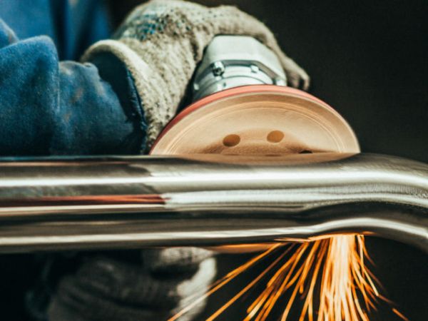
How Do Grinding and Polishing Improve Metal 3D Printed Parts?
After CNC machining creates accurate dimensions, some parts require additional surface finishing.
Grinding and polishing are used when surface quality directly affects performance.
Typical applications include:
- Sealing surfaces
- Sliding contact areas
- Hydraulic components
- Optical housings
- Precision mechanical interfaces
Grinding for Precision Surfaces
Grinding processes include:
- Surface grinding
- Cylindrical grinding
They improve:
- Flatness
- Surface consistency
- Dimensional accuracy
For sealing components, even small surface defects can cause leakage or reduced performance.
For example, a hydraulic manifold may have complex printed internal passages, but the sealing face still needs a very smooth machined and ground surface.
Mechanical, Chemical, and Electrochemical Polishing
Polishing improves both appearance and functional performance.
Common methods include:
- Mechanical polishing
- Chemical polishing
- Electrochemical polishing
These processes are useful for:
- Complex internal channels
- Hydraulic systems
- Medical components
- Corrosion-sensitive parts
Benefits include:
- Lower surface roughness
- Better fluid flow
- Reduced friction
- Improved corrosion resistance
Electrochemical and chemical polishing can reach internal areas that traditional machining tools cannot easily access.
For some applications, internal surface roughness can be reduced below:
Ra < 3 μm
What Role Does Wire EDM Play in Metal 3D Printing Post Processing?
Wire Electrical Discharge Machining (Wire EDM) is mainly used for separation and accurate profile cutting.
Its common applications include:
- Removing parts from the build plate
- Cutting difficult profiles
- Processing thin or complex sections
Wire EDM is not a replacement for CNC machining.
The two processes work together.
| Process | Main Function |
|---|---|
| Wire EDM | Part separation and rough profile cutting |
| CNC Machining | Final precision dimensions and functional features |
A typical production sequence is:
Metal 3D Printing → Wire EDM Separation → CNC Machining → Final Inspection
This combination reduces damage during removal while maintaining final accuracy.
What Is Hybrid Additive and Subtractive Manufacturing?
Hybrid manufacturing combines metal 3D printing and machining in one production system.
This approach is becoming more common in aerospace, industrial manufacturing, and high-value component production.
A hybrid Directed Energy Deposition (DED) system may combine:
- Laser deposition
- CNC milling
- CNC turning
- Grinding
- Preheating
- Powder feeding
- 3D scanning
The biggest advantage is keeping the same machining reference during the entire process.
This reduces:
- Multiple setups
- Transportation between machines
- Alignment errors
- Production delays
A hybrid machine can deposit material in areas where traditional machining cannot create geometry, then machine critical surfaces immediately afterward.
Manufacturing Benefits of Hybrid Processing
Hybrid additive and subtractive manufacturing can provide:
- Tooling cost reduction of 65% or more
- Setup reduction of 70% or more
- Local tolerance capability around ±0.01 mm
- Improved dimensional consistency
For aerospace production, this approach helps companies move from prototype manufacturing toward repeatable production.
What Is the Typical Metal 3D Printing Post Processing Workflow?
A production workflow usually follows several controlled steps.
1. Metal 3D Printing
The part is created using technologies such as:
- Selective Laser Melting (SLM)
- Directed Energy Deposition (DED)
2. Stress Relief and Heat Treatment
Heat treatment reduces internal stress created during printing.
This step is important because residual stress can cause:
- Warping
- Dimensional changes
- Cracking risks
3. Wire EDM Separation
The printed part is removed from the build plate.
4. HIP Processing (When Required)
Hot Isostatic Pressing (HIP) may be used to improve:
- Internal density
- Material performance
- Structural reliability
5. CNC Precision Machining
Machining creates:
- Final dimensions
- Precision holes
- Functional surfaces
6. Grinding and Polishing
Used when applications require:
- Lower roughness
- Better sealing
- Improved surface performance
7. Surface Treatment and Marking
Final steps may include:
- Protective surface treatment
- Identification marking
- Traceability features
8. CMM Inspection
Coordinate Measuring Machine (CMM) inspection verifies:
- Dimensions
- Position accuracy
- Geometric tolerances
How Does Material Choice Affect Machining Strategy?
Different metals behave differently during machining.
The machining process must match material characteristics.
Titanium Alloy Machining
Titanium alloys are widely used in:
- Aerospace components
- Medical implants
- High-performance structures
Challenges:
- High strength
- Poor thermal conductivity
- Tool sticking
- Heat concentration
Recommended strategy:
- Coated carbide tools
- Lower cutting speed
- Higher feed rates
- Strong cooling
Typical reference:
Cutting speed: vc ≈ 30–60 m/min
Thin-wall titanium parts often require:
- Low-temperature cutting
- Micro lubrication (MQL)
- Vibration control
Aluminum Alloy Machining
Aluminum is easier to machine but creates different challenges.
Challenges:
- Material adhesion
- High reflection
- Heat management
Recommended strategy:
- High spindle speed
- Sharp cutting tools
- Proper cooling
Typical reference:
Cutting speed: vc ≈ 200–400 m/min
Stainless Steel 316L Machining
316L stainless steel is common in:
- Medical devices
- Chemical equipment
- Industrial components
Challenge:
- Work hardening
Recommended strategy:
- Sharp cutting tools
- Correct feed rate
- Avoid repeated cutting on hardened areas
Inconel 718 Machining
Inconel 718 is used for:
- Aerospace engines
- High-temperature components
Challenges:
- Difficult machining
- High cutting force
- Fast tool wear
Recommended strategy:
- High-performance tooling
- Low cutting speed
- High torque machining
How Do Manufacturers Control Quality After Machining?
Machining quality depends on measurement and feedback.
After machining, manufacturers use:
- CMM inspection
- Surface roughness measurement
- Dimensional inspection
A modern manufacturing loop connects:
Printing Data
↓
Heat Treatment Results
↓
Machining Process
↓
CMM Measurement
↓
Process Improvement
CMM and Digital Twin Quality Control
Digital twin systems allow manufacturers to compare:
- Original CAD model
- Printed geometry
- Heat treatment deformation
- Final machining results
This helps identify:
- Directional shrinkage
- Process variation
- Repeatability problems
Advanced production lines can send CMM data back into Manufacturing Execution Systems (MES).
This creates:
Print → Heat Treatment → Machining → Measurement → Optimization
A closed-loop manufacturing system.
Common Metal 3D Printing Machining Problems and Solutions
| Problem | Possible Cause | Solution |
|---|---|---|
| Dimension out of tolerance | Incorrect reference or thermal deformation | Check datum and use CMM measurement |
| Vibration marks | Low rigidity or incorrect cutting parameters | Improve tooling and machining conditions |
| Thin-wall deformation | Cutting heat and stress | Use low-temperature cutting and better support |
| Burr formation | Tool path or cutting direction issue | Improve tool movement and add deburring |
| Tool sticking | Material characteristics | Use suitable coatings and cooling methods |
Engineering Recommendations for Metal 3D Printing Machining
Successful metal additive manufacturing requires machining considerations from the design stage.
Recommended practices:
Design machining allowance early
Typical allowance:
0.3–0.5 mm
This provides space for:
- Dimensional correction
- Heat treatment changes
- Final surface improvement
Select machining methods based on features
Examples:
- Complex curves → 5-axis CNC milling
- Rotational parts → CNC turning
- Precision holes → Reaming and boring
- Ultra-smooth surfaces → Grinding and polishing
- Build plate removal → Wire EDM
Match tools and parameters to materials
Titanium, aluminum, stainless steel, and Inconel each require different machining strategies.
Machine after heat treatment
Final machining after thermal processing helps prevent tolerance problems caused by later deformation.
Maintain consistent references
Using the same reference points between printing, machining, and inspection improves accuracy.
Frequently Asked Questions About Metal 3D Printing Post Processing
Why does metal 3D printing require CNC machining?
Short Answer:
Metal 3D printing creates complex shapes, but CNC machining is needed for precision holes, smooth surfaces, threads, and tight tolerances. Machining completes the functional features required for industrial assembly.
Metal printing is excellent for geometry creation. However, production parts often require additional machining because printed surfaces and dimensions may not meet final engineering requirements.
Can metal 3D printing achieve CNC-level accuracy?
Short Answer:
Metal 3D printing can create accurate near-net-shape parts, but CNC machining is usually required to reach tighter tolerances and better surface finishes. Printing creates the structure, while machining creates final precision features.
For applications such as aerospace and medical components, CNC finishing helps achieve reliable assembly and repeatable performance.
What machining process is best for metal 3D printed parts?
Short Answer:
The best machining process depends on part geometry, material, and tolerance requirements. Five-axis milling suits complex shapes, turning suits rotational parts, drilling improves holes, and grinding improves surface quality.
Engineers usually select the process based on the final function of each feature.
Which materials are difficult to machine after metal 3D printing?
Short Answer:
Titanium alloys and Inconel 718 are among the most difficult materials because they generate heat and wear tools quickly. Stainless steel 316L can also be challenging because it becomes harder during machining.
Each material requires specific tools, cutting speeds, and cooling methods.
What is hybrid additive manufacturing?
Short Answer:
Hybrid additive manufacturing combines metal deposition and CNC machining in one workflow. It reduces setups, improves reference accuracy, and helps manufacturers produce complex metal parts faster.
Hybrid systems are especially useful for aerospace and high-value industrial components.
Final Thoughts: Metal 3D Printing and Machining Work Together
Metal 3D printing has changed how engineers create complex components, but machining remains a key step for production-quality parts.
The future of manufacturing is not choosing between additive manufacturing and CNC machining.
It is combining:
- Metal 3D printing
- Precision CNC machining
- Surface finishing
- CMM inspection
- Digital process control
This combination allows manufacturers to produce complex, accurate, and reliable metal components for demanding industries.
About the Author
Felix Lee
CEO at Forgecise
Felix Lee works on advanced manufacturing solutions, metal additive manufacturing workflows, and precision machining strategies for industrial applications. His focus is connecting additive manufacturing technology with practical production requirements.
Through Forgecise, Felix helps manufacturing teams understand how metal 3D printed parts move from printed geometry to finished engineering components.
Reviewed by:
Forgecise Engineering Team
Last Updated: August 10, 2026
Technical Disclaimer:
The machining parameters and process recommendations in this article are general engineering references. Actual machining settings depend on machine capability, tooling selection, material condition, part geometry, and production requirements.