







Back to 3D Printing in Aerospace
Written by Felix Lee
CEO at Forgecise
Felix Lee focuses on advanced manufacturing technologies and industrial engineering solutions. His work explores how additive manufacturing can support lightweight structures, production efficiency, and next-generation aerospace applications.
Last Updated: August 18, 2026
Additive manufacturing lattice structures help UAV and eVTOL manufacturers reduce structural weight while keeping strength, heat control, and electronic protection in one design. By replacing unnecessary solid material with engineered cellular structures, aerospace companies can create lighter components for longer flight time, higher payload capacity, and better electric aircraft performance.
Table of Contents
TL;DR
- Additive manufacturing lattices can reduce aerospace component weight by around 33%–50% compared with traditional designs.
- FCC, Lord Kelvin, Gyroid, Schwarz Diamond, and I-WP structures allow engineers to control strength, stiffness, cooling, and EMI protection.
- Major applications include electric motor housings, propeller hubs, rotor joints, and UAV frame nodes.
- LPBF, SLS, FFF, and other AM methods allow production with metals, polymers, and composite materials.
- Future aerospace production will depend on better simulation, AI-driven design, inspection systems, and process control.
Electric aircraft have one simple problem: every kilogram matters.
Unlike traditional aircraft, UAVs and eVTOL platforms depend heavily on electric power systems. Battery energy density is limited, so reducing structural weight directly improves endurance, payload, hover stability, and operating range.
This is why aerospace engineers are looking beyond traditional manufacturing.
The question is no longer only:
“Can we make this part lighter?”
The better question is:
“Can one part carry loads, remove heat, protect electronics, and reduce assembly at the same time?”
Additive manufacturing lattice structures are designed around this idea.
What Are Additive Manufacturing Lattice Structures?
Additive manufacturing lattice structures are engineered internal frameworks created through 3D printing processes. Instead of producing a fully solid component, engineers place material only where it is needed to carry loads.
These structures use mathematical patterns called lattice topologies.
The final component can have:
- lower weight
- high stiffness
- improved vibration control
- internal cooling paths
- electromagnetic shielding functions
Traditional aerospace manufacturing often relies on CNC machining from solid metal blocks or carbon-fiber layup assemblies.
These methods are reliable, but they have limits.
A machined component removes large amounts of material. Composite structures often require multiple layers, molds, and manual assembly.
Joints create another problem.
Every bracket, bolt, and connection point adds weight and creates possible stress concentration areas.
Additive manufacturing changes the design approach.
Engineers can combine multiple parts into a single printed structure with internal lattice reinforcement.
This reduces:
- fastener weight
- assembly time
- manufacturing complexity
- maintenance difficulty
For UAV and eVTOL manufacturers, this can reduce structural component weight to around one-third to one-half of conventional designs.
Why Do UAV and eVTOL Aircraft Need Lightweight Lattice Structures?
UAV and eVTOL platforms operate under strict weight limits.
A heavier aircraft requires:
- more battery power
- larger motors
- stronger supporting structures
This creates a cycle where extra weight creates even more weight.
Additive lattices break this cycle by improving the strength-to-weight ratio.
The performance of a lattice structure depends on:
- topology design
- relative density
- material selection
- manufacturing process
- print direction
Relative density describes how much material exists compared with a fully solid version of the same material.
A lower relative density means less material, but the structure must still support operational loads.
This balance is the foundation of aerospace lattice design.
Which Lattice Structures Are Used in Aerospace Manufacturing?
Engineers mainly use three lattice families:
- Strut-based lattices
- Plate-based lattices
- Triply Periodic Minimal Surface (TPMS) structures
Each design behaves differently under mechanical loads.
How Does an FCC Lattice Improve Aerospace Structures?
Face-Centered Cubic (FCC) lattices use connected diagonal struts that distribute forces across multiple directions.
When a UAV frame experiences:
- bending loads
- twisting forces
- vibration
the FCC structure spreads those forces through several load paths.
This reduces local stress concentration.
FCC lattices are commonly used for:
- UAV arms
- structural joints
- lightweight frame sections
Typical manufacturing methods include:
- Laser Powder Bed Fusion (LPBF)
- Fused Filament Fabrication (FFF)
Common materials include:
- AlSi10Mg
- Ti-6Al-4V
- carbon-fiber reinforced PA12
Typical relative density:
8%–15%
In optimized multirotor designs, FCC lattices with solid volume fractions as low as 8.75% have achieved stiffness comparable to solid polymer beams while reducing total airframe mass.
Why Is the Lord Kelvin Lattice Used for Aircraft Structures?
The Lord Kelvin truncated-octahedron lattice is designed for bending resistance and energy absorption.
It is useful when structures must resist:
- aerodynamic gust loads
- vibration
- repeated bending forces
Applications include:
- wing structures
- rotor supports
- impact-resistant components
Manufacturing methods include:
- SLS
- LPBF
Materials:
- Nylon 12
- Scalmalloy
- Al2139
Typical relative density:
10%–25%
The geometry helps reduce deformation while keeping the structure lightweight.
Why Are TPMS Lattice Structures Important for Electric Aviation?
Triply Periodic Minimal Surface (TPMS) structures are different from traditional strut lattices.
They are created from mathematical surfaces with smooth continuous curves.
Examples include:
- Gyroid
- Schwarz Diamond
- I-Wrapped Package (I-WP)
Because TPMS structures do not rely on sharp intersections, they can reduce stress concentration and improve fatigue behavior.
Their internal channels also create new possibilities.
The same structure can:
- carry mechanical loads
- move cooling fluid
- improve heat transfer
- absorb electromagnetic waves
This makes TPMS especially attractive for electric aircraft.
What Are the Main TPMS Lattice Types?
Gyroid Structures
Gyroid lattices create continuous internal channels.
Typical manufacturing methods:
- LPBF
- Vat photopolymerization
Materials:
- Ti-6Al-4V
- conductive PLA
- advanced resins
Relative density:
12%–35%
Key benefits:
- smooth stress distribution
- lower fluid pressure loss
- fatigue resistance
- integrated cooling capability
I-WP Structures
I-Wrapped Package lattices provide strong shear performance and good printability.
Typical processes:
- FDM
- LPBF
Materials:
- carbon-black PLA
- AlSi10Mg
Relative density:
10%–30%
Key benefits:
- self-supporting geometry
- shear strength
- EMI absorption capability
Where Are Additive Manufacturing Lattice Structures Used in UAV and eVTOL Aircraft?
The strongest value of additive lattice structures appears in parts where engineers need to solve several problems at once.
These parts usually experience:
- high mechanical loads
- vibration
- heat generation
- limited installation space
- strict weight targets
The three most important application areas are:
- Electric motor housings
- Propeller hubs and rotor components
- UAV and eVTOL structural frame nodes
How Do Additive Motor Housings Improve Electric Aircraft Performance?
Electric motors in UAVs and eVTOL aircraft create large amounts of heat during:
- takeoff
- hovering
- climbing
- high-power operation
High temperatures can damage winding insulation and cause permanent magnet demagnetization.
Traditional motor housings often rely on thick aluminum walls to provide protection and stiffness.
However, thick walls add unnecessary mass.
Additive manufacturing allows engineers to redesign the housing with:
- thin external structural skins
- internal metallic lattice cores
- integrated cooling channels
- conformal heat-transfer paths
For example, LPBF manufacturing can produce aluminum alloy structures such as EOS Al2139.
The material properties described in the report include:
- tensile strength up to 500 MPa
- thermal stability up to 200°C
Inside the housing, engineers can print:
- helical cooling passages
- lattice heat sinks
- internal thermal pathways
The result is a structure that does more than protect the motor.
It also removes heat.
Using conductive lattice cores increases surface area for heat transfer while reducing housing mass by more than 40% compared with traditional designs.
How Do Lattice Structures Improve Propeller Hubs and Rotor Systems?
Propeller hubs and rotor blade connections operate under difficult conditions.
They experience:
- centrifugal forces
- gyroscopic loads
- repeated vibration
- aerodynamic cycling
A traditional solid hub must be strong enough everywhere.
A lattice-based hub places material only where loads require it.
This allows engineers to tune:
- stiffness
- vibration behavior
- rotational inertia
One important factor is the polar moment of inertia (J).
A lower rotational inertia allows:
- faster motor response
- lower current demand during throttle changes
- better flight-control performance
This is especially useful in advanced designs such as toroidal propellers.
Toroidal propellers use a closed-loop blade design where blade tips connect back into the central hub.
Additively manufactured hubs using:
- LPBF AlSi10Mg
- SLS Nylon 12
can include internal lattice voids that reduce unnecessary mass.
Engineers can also place viscoelastic damping materials inside lattice spaces.
This helps reduce vibration transmission into:
- motor bearings
- aircraft frames
- avionics systems
How Do Additive Lattices Improve UAV Frame Nodes?
Structural connection points are some of the most difficult areas in aircraft design.
A traditional multirotor frame often uses:
- carbon-fiber tubes
- CNC aluminum connectors
- mechanical clamps
- fasteners
The problem is that every connection creates:
- additional weight
- stress concentration
- assembly complexity
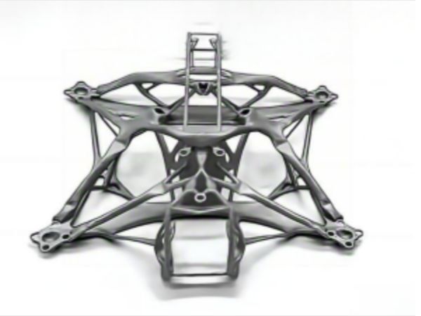
Additive manufacturing allows engineers to create continuous structures.
A central fuselage node can transition directly into hollow lattice-reinforced boom arms.
This approach is useful for advanced multirotor systems, including configurations such as:
- PTX6
- PTX8
These aircraft require complex angled connections that are expensive to machine using traditional methods.
Printed structures can also include internal channels for:
- high-voltage ESC cables
- power wiring
- cooling paths
The structure becomes part of the aircraft’s electrical and thermal system.
Can Additive Lattice Structures Provide EMI Shielding and Thermal Management?
Yes.
One of the biggest advantages of aerospace lattices is that they can combine multiple functions inside one component.
A single printed structure can act as:
- a load-bearing component
- a cooling system
- an EMI protection layer
This reduces the need for separate parts.
How Do Lattice Structures Protect Aircraft Electronics From EMI?
Electric aircraft rely on powerful electronic systems.
High-frequency switching from:
- motor controllers
- ESC systems
- power electronics
can create electromagnetic interference.
This interference may affect:
- flight computers
- navigation systems
- communication equipment
Traditional EMI protection often uses:
- metal shielding boxes
- copper tape
- additional conductive layers
These solutions work but add weight.
Additive lattices offer another approach.
Metal lattices and conductive polymer structures can absorb electromagnetic energy.
Materials can include:
- carbon-black reinforced polymers
- carbon nanotube materials
- conductive PLA
- metallic lattice structures
The internal geometry creates repeated electromagnetic reflections.
During this process, electromagnetic energy is converted into heat.
The report describes an I-WP TPMS lattice with a density gradient from:
10% to 30%
achieving electromagnetic absorption above:
90% between 3.53 GHz and 24.00 GHz
This covers:
- C band
- X band
- Ku band
These structures could be integrated into:
- avionics enclosures
- motor covers
- wing structures
without adding separate shielding components.
How Do Additive Lattices Improve Aircraft Thermal Management?
Electric aircraft have limited space around motors and power systems.
Traditional heat sinks are often flat and difficult to integrate into curved aerospace structures.
Metal additive manufacturing allows engineers to create:
- curved cooling channels
- internal lattice heat exchangers
- conformal cooling systems
Liquid cooling systems can move coolant through TPMS structures inside a motor housing.
The large internal surface area improves heat transfer.
Air-cooled systems can use open-cell conductive lattice structures placed inside propeller airflow.
This provides forced-air cooling without large external heat sinks.
What Are the Main Engineering Challenges Before Aerospace Production?
Additive lattice structures show strong laboratory results, but aerospace production requires strict engineering control.
A printed prototype is not automatically a flight-ready component.
The industry faces five major challenges.
Challenge 1: How Do Engineers Improve Fatigue Life?
One major issue in metal AM is surface quality.
During LPBF manufacturing, partially melted powder particles can remain attached to thin lattice struts.
These small surface defects behave like microscopic cracks.
Under repeated vibration, they can become fatigue failure points.
Engineers address this through:
- smoother lattice geometry
- larger fillet transitions
- optimized strut-node connections
- surface finishing
- Hot Isostatic Pressing (HIP)
Software platforms such as nTop allow designers to create smoother implicit lattice structures.
After printing, processes such as:
- chemical polishing
- electropolishing
can remove surface defects.
HIP treatment helps close internal pores and improve fatigue performance.
However, aerospace teams must still create fatigue data from parts printed in the actual build direction.
Standard solid metal data is not enough.
Challenge 2: How Do Manufacturers Remove Trapped Powder and Resin?
Internal lattice structures can create another manufacturing problem.
When a lattice is enclosed inside solid outer walls, unused powder or resin may become trapped.
This creates:
- extra unwanted mass
- cleaning difficulty
- possible flight risks if material moves internally
The solution begins during design.
Engineers must include:
- powder evacuation paths
- drainage openings
- continuous internal channels
TPMS designs such as:
- Gyroid
- Schwarz Diamond
are useful because they create connected pathways.
The report recommends internal clearance around:
1.2 mm–1.5 mm
for effective material removal.
Post-processing can include:
- multi-axis vibration systems
- ultrasonic fluid cleaning
before final heat treatment.
Challenge 3: Why Can Simulation Results Differ From Real Testing?
Many traditional engineering simulations assume materials behave the same in every direction.
Additive manufacturing materials often do not.
Layer-by-layer printing creates different properties depending on:
- build direction
- thermal history
- layer bonding
This creates material anisotropy.
The Z direction may have different strength compared with horizontal directions.
Better simulation requires:
- orthotropic material models
- build-direction data
- printed test coupons
Advanced workflows can connect printing paths with simulation software and assign different stiffness values to different lattice regions.
Physical testing should establish:
- tensile strength
- compression strength
- shear strength
for the actual manufacturing process.
The report references composite-style testing methods such as ASTM D3039 for material validation.
Challenge 4: How Can Electric Aircraft Balance Cooling and Sealing?
Electric propulsion systems need two things that conflict:
They need to stay cool.
They also need protection from:
- moisture
- dust
- environmental exposure
A fully sealed housing improves protection, but it traps heat.
Adding liquid cooling systems can solve the heat problem but adds:
- pumps
- radiators
- fluid lines
This can reduce the weight savings achieved by additive manufacturing.
A hybrid solution uses materials such as:
- Scalmalloy
- Al2139
The design combines:
- solid external sealing surfaces
- internal lattice heat-transfer structures
- external cooling fins
The propeller airflow can provide additional cooling without requiring a heavy active system.
Challenge 5: How Can Polymer Aircraft Structures Reduce EMI Problems?
Polymer structures such as:
- PA12
- carbon-fiber PETG
can reduce aircraft weight.
However, polymers provide less natural electromagnetic protection than aluminum.
Adding external shielding layers increases:
- weight
- assembly work
- manufacturing complexity
Multi-material additive manufacturing provides another option.
Manufacturers can print:
- structural carbon-fiber polymer sections
- conductive internal pathways
using materials containing:
- graphene
- carbon black
Another method is embedding thin metallic lattice inserts inside composite walls.
The report describes this approach as creating an integrated Faraday cage with more than:
20 dB electromagnetic attenuation
across operating frequency ranges.
What Aerospace Case Studies Show the Potential of Additive Lattices?
Real-world demonstrations show that additive manufacturing is moving beyond simple prototypes.
Lawrence Livermore National Laboratory (LLNL)
LLNL engineers developed additive manufacturing approaches for:
- motor arm covers
- hybrid engine cooling mounts
The goal was to protect electrical components while managing heat during high-power operation.
The integrated cooling approach showed how printed structures can combine protection and thermal control.
3DFiT Unibody Drone Frame
The 3DFiT project tested a continuous composite drone frame with internal FCC lattice reinforcement.
Compared with a traditional DJI F450-style frame, the design achieved:
- about 10% mass reduction
- fewer mechanical fasteners
- reduced joint movement
- improved load transfer at arm connections
Toroidal Propeller Manufacturing
Research comparing conventional propellers with additive toroidal propeller designs found several benefits.
LPBF AlSi10Mg versions demonstrated:
- yield strength around 240 MPa
- elastic modulus around 70 GPa
The closed-loop geometry reduced blade-tip vortex formation and helped lower high-frequency noise during hover.
The reported aerodynamic figure of merit was approximately:
FM ~0.45
Embedded Conductive Wiring Structures
Multi-material FFF trials demonstrated that manufacturers can print conductive pathways inside structural parts.
This creates:
- integrated power routes
- ESC signal pathways
- reduced wiring harness complexity
The result is simpler assembly and fewer separate components.
How Do Aerospace Companies Control the Quality of Additive Lattice Parts?
Moving additive lattice structures from prototypes into aircraft production requires strict control.
A successful printed part is not only about geometry.
Aerospace manufacturers also need:
- repeatable production
- material traceability
- defect detection
- process monitoring
- reliable testing data
Aerospace standards such as AS9100D require manufacturers to control every step of production.
This becomes more difficult with lattice structures because many important features are hidden inside the component.
A small thermal change during printing can affect thin lattice struts.
Problems may come from:
- unstable powder-bed conditions
- recoater movement
- laser energy variation
- uneven thermal distribution
These issues can create internal defects that are difficult to see from the outside.
How Does In-Situ Monitoring Improve Additive Manufacturing Quality?
Modern LPBF systems are adding closed-loop monitoring to improve production reliability.
The report highlights systems such as EOS Smart Fusion, which uses:
- optical pyrometry
- melt-pool monitoring
- layer-by-layer thermal analysis
The system watches thermal behavior during printing.
If the machine detects unusual heat patterns or local overheating, it can adjust laser settings during the build.
This helps reduce:
- thermal distortion
- inconsistent density
- manufacturing defects
For aerospace production, this type of monitoring creates a digital record of how each component was produced.
Why Are CT Scanning and HIP Important for Aerospace Lattice Parts?
Traditional inspection methods cannot always see inside complex lattice structures.
A component may look perfect externally while containing:
- internal pores
- incomplete fusion
- trapped powder
- hidden defects
Non-destructive CT scanning allows engineers to inspect internal geometry without cutting the part apart.
For metal structural components, the report recommends combining:
- CT inspection
- physical testing
- Hot Isostatic Pressing (HIP)
- process monitoring
This creates a stronger qualification path for flight hardware.
How Are AI and Generative Design Changing Aerospace Lattice Engineering?
Complex lattice structures can contain millions of surfaces and connection points.
Traditional CAD systems based on boundary representation (B-Rep) can become slow and difficult to manage.
Modern implicit modeling systems solve this problem differently.
Instead of manually drawing every strut, engineers define mathematical rules that generate the structure.
This allows:
- faster topology optimization
- smoother density changes
- easier design changes
- complex internal geometries
For example, engineers can gradually change lattice density from a lightweight region to a high-strength region without creating sharp transitions.
How Is AI Helping Develop New Aerospace Materials?
AI is also being used beyond geometry design.
Machine learning systems can analyze:
- powder chemistry
- printing parameters
- build history
- material performance data
This helps researchers discover printable materials faster.
The report notes that AI approaches have reduced development cycles for some advanced materials, including:
- High-Entropy Alloys (HEAs)
- Nickel-Titanium (NiTi) shape-memory alloys
by around 50%.
These materials may provide:
- higher strength-to-weight ratios
- better temperature performance
- vibration damping ability
This could expand where additive lattices can be used in future electric aircraft.
How Should UAV and eVTOL Companies Implement Additive Lattice Technology?
Companies should not begin by printing every component.
The better approach is selecting parts where additive manufacturing creates the highest engineering value.
The goal is not simply replacing a traditional part with a printed version.
The goal is redesigning the system.
1. Start With High-Value Structural Areas
The best first targets are components where weight savings create wider aircraft benefits.
Examples:
- motor housings
- propeller hubs
- fuselage connection nodes
- rotor arm structures
These parts already need:
- mechanical strength
- thermal control
- vibration management
- electrical integration
A single multifunctional printed component can replace several separate parts.
2. Choose the Right Additive Manufacturing Process
Different components require different manufacturing methods.
For high-load aerospace structures:
LPBF
is suitable for materials such as:
- AlSi10Mg
- Scalmalloy
- Ti-6Al-4V
Typical applications:
- structural nodes
- motor housings
- rotor components
For lower-load components:
SLS
with materials such as:
- PA11
- PA12
can be suitable for:
- fairings
- electronics housings
- ducts
The process must match the engineering requirement.
3. Design for Additive Manufacturing From the Beginning
One of the biggest mistakes companies make is designing a traditional part first and trying to print it later.
Additive manufacturing works best when engineers consider the process from the start.
Important design factors include:
- build orientation
- lattice density
- strut thickness
- support requirements
- powder removal paths
- drainage holes
- fatigue behavior
Design for Additive Manufacturing (DfAM) should be part of the original engineering workflow.
4. Build a Strong Inspection and Validation System
Aerospace buyers need confidence that every printed part performs consistently.
Production contracts should define:
- in-situ monitoring requirements
- CT inspection standards
- material traceability
- fatigue testing procedures
- HIP requirements where needed
Qualification is not only about producing a strong prototype.
It is about producing the same quality part thousands of times.
What Is the Future of Additive Manufacturing Lattice Structures in Electric Aviation?
The future aircraft structure will not simply be lighter.
It will become smarter.
A printed motor housing may also become:
- a cooling system
- an electromagnetic shield
- a structural support
A boom arm may also become:
- a cable pathway
- a power distribution structure
- a vibration-control component
A structural panel may also manage:
- heat flow
- electromagnetic signals
- weight distribution
This change comes from combining:
- lattice engineering
- multi-material printing
- AI design tools
- advanced materials
- process monitoring
The biggest shift is in how engineers think about aircraft parts.
The future question is not:
“Which parts can we 3D print?”
It is:
“Which systems can we combine into one qualified multifunctional structure?”
That is where additive manufacturing lattice technology creates the most value for UAV and eVTOL development.
Frequently Asked Questions
What Are Additive Manufacturing Lattice Structures?
Short answer:
Additive manufacturing lattice structures are lightweight internal frameworks created through 3D printing. They replace unnecessary solid material with engineered patterns that maintain strength while reducing weight.
These structures use designs such as FCC, Lord Kelvin, Gyroid, Schwarz Diamond, and I-WP lattices.
Engineers can adjust their density and geometry to control:
- stiffness
- strength
- vibration response
- heat transfer
- electromagnetic protection
For aerospace applications, lattices help create lighter UAV and eVTOL components without simply making parts thinner or weaker.
How Do Lattice Structures Reduce UAV and eVTOL Weight?
Short answer:
Lattice structures reduce aircraft weight by placing material only where loads require support instead of filling the entire component with solid material.
A traditional metal block contains material that may not contribute to structural performance.
A lattice design removes unnecessary mass while keeping important load paths.
The report identifies structural weight reductions of around 33%–50% compared with conventional designs.
The actual result depends on:
- material
- geometry
- safety requirements
- manufacturing method
- testing standards
Which Lattice Designs Are Used in Aerospace Manufacturing?
Short answer:
The most common aerospace lattice designs include FCC, Lord Kelvin, and TPMS structures such as Gyroid and I-WP.
FCC structures work well for multi-directional loads.
Lord Kelvin structures provide bending resistance and energy absorption.
TPMS structures create smooth continuous surfaces that support:
- fatigue performance
- fluid flow
- thermal management
- EMI absorption
The correct design depends on the aircraft component and operating conditions.
Can 3D Printed Lattice Parts Replace Traditional Aircraft Components?
Short answer:
Yes, but only after engineering validation and qualification.
Additive lattice parts can replace or combine traditional components such as:
- brackets
- housings
- frame nodes
- cooling structures
However, aerospace companies must verify:
- fatigue life
- material behavior
- production consistency
- internal quality
- certification requirements
A printed prototype is only the first step.
What Are the Biggest Challenges for Aerospace Additive Manufacturing?
Short answer:
The main challenges are fatigue performance, powder removal, simulation accuracy, thermal management, EMI protection, and production quality control.
Engineers must solve issues caused by:
- surface roughness
- layer-based material behavior
- trapped powder
- internal defects
- environmental sealing requirements
The industry is addressing these challenges through better materials, improved software, monitoring systems, and stronger validation methods.