








Back to 3D Printing in Aerospace
Written by Felix Lee
CEO at Forgecise
Published: August 18, 2026
Last Updated: August 18, 2026
Table of Contents
Quick Answer
Additive manufacturing for aircraft nacelle structures uses metal 3D printing and topology optimization to create lighter, stronger aerospace components. Technologies such as LPBF and EBM allow engineers to reduce material waste, improve structural efficiency, and combine multiple parts into single optimized designs.
Key Takeaways
- Aircraft nacelles require strong structures that can handle vibration, heat, and aerodynamic forces.
- Topology optimization helps engineers remove unnecessary material while maintaining strength.
- LPBF, EBM, and DMLS enable complex aerospace parts that traditional machining cannot easily produce.
- Airbus and Safran have already applied additive manufacturing to nacelle-related components.
- Certification, fatigue testing, and production control remain major requirements before wider adoption.
Why Are Aircraft Nacelle Structures Moving Toward Additive Manufacturing?
Aircraft nacelles are not simple covers around engines. They are structural systems that support fairings, hinges, brackets, and other load-carrying components.
During flight, these structures experience:
- High-speed airflow forces
- Engine vibration
- Acoustic loads
- Thermal changes
- Repeated mechanical stress
Traditional manufacturing methods include CNC machining from metal billets, casting, and welded sheet-metal assemblies.
These methods work well, but they limit designers.
A machined part often needs extra material because cutting tools cannot reach every area. Cast parts also require designs that fit manufacturing limits.
Metal additive manufacturing changes this approach.
Instead of removing material from a large block, engineers create parts based on actual load requirements.
This allows aerospace companies to produce:
- Lighter structures
- More efficient load paths
- Fewer assembled parts
- Lower material waste
How Does Topology Optimization Improve Aerospace Structures?
Topology optimization uses computer simulation to find where material is needed and where it can be removed.
The basic idea is simple:
A structure should carry loads efficiently, not simply contain as much material as possible.
Traditional design often follows manufacturing rules.
Topology optimization follows structural behavior.
From Solid Blocks to Optimized Load Paths
A conventional nacelle bracket may start as a solid metal shape.
However, stress is not distributed equally.
Some areas carry major forces.
Other areas add weight without improving performance.
Topology optimization removes low-value material and creates organic structures similar to lightweight truss systems.
Common optimization methods include:
SIMP (Solid Isotropic Material with Penalization)
SIMP adjusts material density inside finite element models while reducing structural compliance.
Evolutionary Structural Optimization (ESO)
ESO removes material step by step while keeping the required strength.
Level-Set Optimization
This method changes the outer boundary shape of a structure to improve performance.
For nacelle hinges, actuator supports, and fairing brackets, these methods help engineers create efficient designs that match real stress paths.
How Does Additive Manufacturing Reduce Aerospace Material Waste?
A major benefit of aerospace additive manufacturing is a lower Buy-to-Fly ratio.
Buy-to-Fly describes the amount of raw material purchased compared with the final aircraft component weight.
Traditional Manufacturing
Titanium and nickel alloy parts made from billets often have:
Buy-to-Fly ratio: 15:1 to 40:1
Large amounts of expensive material become machining waste.
Additive Manufacturing
LPBF and EBM create parts close to their final shape.
Typical:
Buy-to-Fly ratio: 1.1:1 to 3:1
Benefits:
- Less raw material waste
- Lower machining requirements
- Better use of expensive aerospace alloys
- Reduced manufacturing waste
Which Materials Are Used for Aircraft Nacelle Additive Manufacturing?
Material choice depends on:
- Temperature range
- Mechanical loads
- Weight targets
- Vibration conditions
- Connection requirements with composite structures
| Material | Density | Strength | Temperature Range | Applications |
|---|---|---|---|---|
| AlSi10Mg | 2.67 g/cm³ | 330–460 MPa UTS | Up to 150°C | Fairing brackets and mounts |
| Scalmalloy® | 2.67 g/cm³ | 480–520 MPa UTS | Up to 200°C | Lightweight structural supports |
| Ti-6Al-4V | 4.43 g/cm³ | 900–1150 MPa UTS | 350–400°C | Hinges and attachment points |
| Inconel 718 | 8.19 g/cm³ | 1200–1400 MPa UTS | Up to 650°C | Heat-resistant nacelle hardware |
Why Is Scalmalloy Important for Lightweight Aerospace Parts?
Scalmalloy is an aluminum-magnesium-scandium-zirconium alloy developed for high-performance additive manufacturing.
During LPBF processing, rapid cooling creates a fine microstructure.
After heat treatment, nanoscale Al₃(Sc,Zr) particles improve:
- Grain stability
- Strength
- Crack resistance
Scalmalloy can reach yield strength close to 480 MPa while maintaining aluminum-like density.
Its specific yield strength:
179.8 MPa/(g/cm³)
Ti-6Al-4V remains stronger:
203.1 MPa/(g/cm³)
However, for structures operating below approximately 200°C, Scalmalloy can replace heavier titanium parts in some applications.
How Has Airbus Used Additive Manufacturing for Nacelle Components?
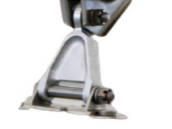
One well-known example is the Airbus A320 nacelle hinge bracket.
The original component used investment-cast steel.
The bracket:
- Connected engine cowl doors
- Experienced vibration loads
- Required long fatigue life
The redesigned component used:
- DMLS manufacturing
- Ti-6Al-4V material
- Topology optimization
Results:
| Feature | Original | Optimized AM |
|---|---|---|
| Material | Cast Steel | Ti-6Al-4V |
| Weight | 544 g | 196 g |
| Weight Reduction | — | 64% |
| Stiffness | Baseline | 40% improvement |
For four brackets per aircraft engine installation:
Weight saving:
Approximately 1.392 kg
Over long aircraft service periods, small weight reductions can reduce fuel use and operating costs.
How Is Safran Nacelles Applying Additive Manufacturing?
Safran Nacelles has applied additive manufacturing in commercial aircraft and business jet propulsion systems.
Programs connected with:
- Clean Sky 2
- Clean Aviation
- NIPSE
have studied ways to reduce equipment size and improve nacelle integration.
The NIPSE program achieved:
- About 10% reduction in equipment volume and mass
- Around 40% reduction in routing development time
Safran also worked with AnyShape on LPBF AlSi10Mg drilling fixtures for the Rolls-Royce Pearl 700 nacelle program.
These tools improved:
- 90° drilling accuracy
- Assembly tolerance control
- Manufacturing consistency
What Are the Main Challenges of Aerospace Additive Manufacturing?
Metal additive manufacturing has proven that it can create strong and lightweight aerospace structures. However, moving from prototypes to flight-ready components requires solving several engineering challenges.
The biggest challenges include:
- Designing parts that can actually be printed
- Controlling fatigue performance
- Managing production costs
- Meeting aviation certification requirements
Why Must Topology Optimization Be Combined With Design for Additive Manufacturing (DFAM)?
Topology optimization does not automatically create a production-ready aerospace component.
A computer-generated structure may look efficient, but it can create manufacturing problems such as:
- Difficult support requirements
- Unreachable machining areas
- Trapped powder inside cavities
- Weak stress concentration points
This is why aerospace engineers use Design for Additive Manufacturing (DFAM) after optimization.
DFAM converts optimized shapes into practical production parts.
Important DFAM rules include:
Self-Supporting Geometry
For metal LPBF production, engineers often design structures with overhang angles greater than:
45° relative to the build platform
This reduces the amount of support material required.
Machining Allowances
Critical surfaces need additional material after printing.
Typical allowance:
1.5–3.0 mm
Used for:
- Bolt holes
- Pin locations
- Precision mounting faces
- Threaded areas
These areas can then receive final CNC machining.
Powder Removal Design
Internal cavities must allow unused powder to escape.
Poor powder drainage can create:
- Additional weight
- Inspection problems
- Internal contamination risks
How Do Aerospace Companies Improve Fatigue Performance in Metal AM Parts?
Fatigue performance is one of the most important concerns for flight hardware.
Aircraft nacelle components experience millions of vibration cycles during service.
As-built LPBF surfaces usually have:
Surface roughness: Ra ≈10–25 μm
The rough surface can create small stress concentration points.
Compared with traditional wrought materials, fatigue performance may decrease by:
30–50%
because of:
- Surface roughness
- Internal pores
- Lack-of-fusion defects
How Are AM Components Improved After Printing?
Flight-critical aerospace parts normally require post-processing.
Hot Isostatic Pressing (HIP)
HIP uses high temperature and pressure to close internal defects.
Typical titanium HIP conditions:
- Temperature: 900–1000°C
- Argon pressure: 100–150 MPa
Benefits:
- Removes internal voids
- Improves material density
- Increases reliability
Target density:
Above 99.92%
Surface Finishing Methods
Common finishing processes include:
- CNC machining
- Shot peening
- Abrasive flow machining
- Chemical polishing
The goal is to reduce surface roughness.
Typical target:
Ra <1.6 μm
These treatments improve fatigue resistance by reducing crack initiation points.
How Are Nacelle Components Tested Under Real Flight Loads?
Nacelle support structures experience complex loading conditions.
Engineers must consider:
- Aerodynamic drag
- Engine thrust forces
- Thermal expansion
- Acoustic vibration
- Landing impact loads
These forces are often combined in finite element analysis (FEA).
A bracket is not tested only for one direction of force.
It must survive multiple load cases at the same time.
Aerospace Safety Factors and Load Requirements
Civil and military aerospace structures use strict safety margins.
Typical requirements include:
- Ultimate factor of safety: 1.50
- Yield margin: 1.15–1.25
Testing may include:
- Static load testing
- Dynamic vibration testing
- Fatigue spectrum testing
For advanced qualification, engineers evaluate:
- Multi-axis loads
- Structural deformation
- Crack growth behavior
Is Additive Manufacturing Cheaper Than Traditional Aerospace Manufacturing?
The answer depends on the part.
Metal additive manufacturing is not automatically cheaper than machining or casting.
Material costs can be higher.
For example:
- Scalmalloy powder can exceed $200/kg
- Conventional aluminum stock is much cheaper
However, cost cannot be measured only by production price.
The complete business case includes:
- Less material waste
- Fewer assembled parts
- Reduced tooling requirements
- Lower inspection and assembly work
- Aircraft fuel savings over decades
When Does Aerospace AM Make Economic Sense?
Additive manufacturing is most valuable for components that have:
- Complex geometry
- High material value
- Low-to-medium production volume
- Large weight reduction opportunities
A simple aluminum bracket may still be cheaper to machine.
A complex titanium structure with many assembled parts may be a strong AM candidate.
How Are Additively Manufactured Aircraft Components Certified?
Certification is one of the most important steps before AM parts enter commercial aircraft service.
Unlike traditional materials, additive manufacturing properties depend on:
- Machine settings
- Powder quality
- Build direction
- Thermal processing
Because of this, aerospace regulators require detailed qualification programs.
Which Aerospace Standards Support Metal Additive Manufacturing?
Important standards include:
| Standard | Organization | Purpose |
|---|---|---|
| FAA Draft AC 20-191 | Federal Aviation Administration | Guidance for additive manufactured flight hardware |
| FAA PS-ANM-25-12 | FAA | Fatigue and damage tolerance evaluation |
| SAE AMS7000 | SAE International | LPBF process control |
| SAE AMS7001 | SAE International | Nickel alloy AM requirements |
| SAE AMS7002 / AMS7003 | SAE International | Powder quality and recycling control |
| SAE AMS7004 / AMS7005 | SAE International | Heat treatment and HIP procedures |
These standards help control:
- Material consistency
- Powder quality
- Manufacturing repeatability
- Post-processing requirements
What Is the Aerospace Additive Manufacturing Qualification Process?
Aerospace companies usually follow a four-level building-block testing approach.
Level 1: Material Coupon Testing
Engineers print thousands of small test samples.
Testing covers:
- Different machines
- Different build directions
- Different powder batches
The goal is to establish reliable material design values:
- A-basis allowables
- B-basis allowables
Level 2: Structural Element Testing
Engineers test smaller structural details such as:
- Fastener locations
- Pin joints
- Lattice connections
This identifies local stress behavior.
Level 3: Sub-Component Testing
Full structural parts are tested.
Examples:
- Nacelle hinge fittings
- Fairing brackets
Testing includes:
- Hydraulic loading
- Vibration testing
- High-load conditions
Level 4: Full Assembly and Flight Validation
The final stage includes:
- Aircraft integration
- Flight testing
- Non-destructive inspection
Inspection methods include:
- Ultrasonic testing
- Computed Tomography (CT)
What Is the Future of Additive Manufacturing for Aircraft Nacelle Structures?
The next stage of aerospace manufacturing will combine:
- Metal additive manufacturing
- Artificial intelligence
- Generative design
- Digital engineering
- Automated inspection
Future nacelle structures will likely use fewer parts and more integrated designs.
The biggest change is not the printer itself.
The bigger change is the design mindset.
Engineers are moving from:
“ How can we manufacture this existing part?”
to:
“ What is the most efficient structure for this aircraft system?”
That shift creates opportunities for lighter aircraft, lower fuel consumption, and more efficient production.
Frequently Asked Questions
What is additive manufacturing for aircraft nacelle structures?
Additive manufacturing for aircraft nacelle structures is the use of metal 3D printing technologies such as LPBF and EBM to produce engine exterior brackets, supports, and fairing components. It allows engineers to create lightweight structures with optimized geometry while reducing material waste compared with traditional manufacturing.
How does topology optimization help aerospace engineers?
Topology optimization uses computer simulation to remove unnecessary material while keeping required strength and stiffness. It identifies efficient load paths and creates lightweight structures that are difficult to manufacture using traditional machining or casting methods.
Which metals are used for aircraft nacelle additive manufacturing?
Common materials include AlSi10Mg, Scalmalloy®, Ti-6Al-4V, and Inconel 718. Aluminum alloys are used for lighter low-temperature applications, titanium is used for stronger structural points, and nickel alloys support higher-temperature environments.
Why is certification difficult for aerospace 3D printing?
Certification is challenging because AM material properties can change depending on machine settings, powder quality, build direction, and heat treatment. Aerospace companies must prove repeatable performance through extensive testing before flight approval.
Is metal additive manufacturing replacing traditional aerospace manufacturing?
Metal additive manufacturing is not replacing every traditional process. It works best for complex, lightweight, high-value components where design freedom, reduced assembly, and lifecycle savings provide advantages.
Author Information
Written by Felix Lee
Felix Lee is the CEO at Forgecise, focusing on advanced manufacturing technologies, industrial innovation, and engineering solutions. His work covers the adoption of next-generation manufacturing methods that help companies improve product design, efficiency, and production performance.
Technical Review Note
This article is based on aerospace additive manufacturing concepts including:
- LPBF and EBM processes
- Topology optimization methods
- Aerospace alloy selection
- Nacelle structural applications
- AM qualification practices
Technical details were organized for engineering decision-makers, manufacturing teams, and aerospace professionals.
Disclaimer
This article provides general technical information about aerospace additive manufacturing. Aircraft component design, testing, and certification must follow approved engineering procedures and aviation authority requirements.