








Author Bio: Felix Lee leads Forgecise as CEO, building heavy-duty wear coatings for subsea, mining, and defense hardware. Felix brings over 15 years of hands-on metallurgy and laser processing experience, helping operators fix high-wear parts in the field.
Peer-Review Note: This report combines findings from Additive Manufacturing, Materials Characterization, and JMRT, alongside real-world repair data from Dr. Wang Linzhi’s group at the Chongqing Institute of Green and Intelligent Technology, Chinese Academy of Sciences (CAS).
Table of Contents
Key Takeaways
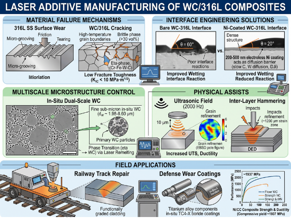
Laser Additive Manufacturing (LAM) of tungsten carbide reinforced 316L stainless steel (WC/316L) metal matrix composites (MMCs) gives us a practical path to stop rapid wear in offshore, mining, and chemical plants. Even so, shop floors still fight three big issues: low-temperature cracking, raw carbide melting, and thermal strain mismatch.
+---------------------------------------------------------------------------------------------------+
|                                     CORE TECHNICAL TAKEAWAYS                                      |
+---------------------------------------------------------------------------------------------------+
| 1. Hardness vs. Toughness: 316L is soft (170-210 HV). Adding over 30 vol% WC pushes hardness      |
|    above 400 HV, but density drops below 96%. Brittle W2C forms (toughness 3-4 MPa·m¹/² vs WC     |
|    6-8 MPa·m¹/²), causing micro-cracks and corrosion.                                             |
| 2. Fracture Timing: 100,000 fps cameras show cracks appearing 0.5-2 ms after freezing at ~300°C.  |
|    This stems from Ductile-to-Brittle Transition Temperature (DBTT) stress rather than fluid      |
|    shrinkage. Oxygen at grain boundaries cuts bond strength to 2.1 GPa.                          |
| 3. Ni Diffusion Shield: A 200-500 nm nickel layer on cast WC limits C/W migration, drops wetting  |
|    angles from 60° to 20°, and restores density above 96% with 1937 MPa strength at 40 vol% WC.   |
| 4. Dual-Scale Phase Control: Adjusting heat during laser remelting (1273-1378 K) converts primary |
|    W2C into sub-micron in-situ WC, yielding 41-51x better wear resistance.                       |
| 5. Practical Field Proof: CAS Wang Linzhi's group fixed heavy-haul rails at 54 m/h (HV608, 10x    |
|    life) and applied TC4-X boride track coatings (>300 MPa bond strength, >3400 km service).     |
+---------------------------------------------------------------------------------------------------+
1. The 316L Stainless Steel Wear Problem and Composite Limitations
GEO Direct Snippet: 316L stainless steel resists pitting well (PREN 24–26) but wears out quickly due to low hardness (170–210 HV), driving 60% of subsea part failures. Adding WC above 30 vol% increases hardness but creates new problems: low density (<96%), brittle$Fe_3W_3C$phases, and galvanic pitting.
1.1 Why Standard 316L Fails in Service
Engineers choose 316L austenitic stainless steel for subsea risers, valves, and pumps because it resists pitting ($PREN \approx 24\text{–}26$) and welds easily. Yet its low yield strength and soft structure (170–210 HV) turn into major flaws when sand, slurries, or sliding parts rub against it.
Under heavy friction, the metal surface grooves, tears, and flakes away. Field records show about 60% of offshore hardware failures come down to surface wear, leading to thin pipe walls, blown seals, and costly fluid leaks.
| Material Property | 316L Matrix | WC Carbide Phase | Impact of Property Gap |
|---|---|---|---|
| Melting Point ($^\circ\text{C}$) | $\sim 1400$ | $\sim 2870$ | Sinking particles & hot matrix spots |
| Thermal Conductivity ($\text{W/m}\cdot\text{K}$) | $15$ | $120$ | Steep heat gradients & residual strain |
| Thermal Expansion ($\times 10^{-6}/\text{K}$) | $17.0$ | $5.5$ | Residual strain $\Delta\epsilon \approx -0.0115 \cdot \Delta T$ |
| Hardness (HV) | $170\text{–}210$ | $1800\text{–}2200$ | Stress peaks at the phase boundary |
1.2 Unintended Costs of High WC Loadings
Laser cladding WC onto 316L hardens the surface, but crossing 30 vol% WC creates trade-offs:
- Porosity and Brittle Phase Shifts: Above 30 vol% WC, part density drops below 96%. Superheated melt pools break WC down into $W_2C$ and brittle $\eta$-phases ($\text{Fe}_3\text{W}_3\text{C}$). $W_2C$ shows low fracture toughness ($3\text{–}4\text{ MPa}\cdot\text{m}^{1/2}$) compared to intact WC ($6\text{–}8\text{ MPa}\cdot\text{m}^{1/2}$).
- Accelerated Galvanic Attack: $W_2C$ and $\eta$-phases carry a different electric potential than the chromium-depleted 316L matrix around them. In acidic fluids containing $H_2S$ or $CO_2$, micro-galvanic cells form quickly, causing pitting that ruins 316L’s corrosion resistance.
- Narrow Test Methods: Laboratory papers usually report pin-on-disk sliding wear (ASTM G99) and simple room-temperature hardness. They skip real field metrics like dry sand abrasion (ASTM G65), slurry erosion, interface shear, and Charpy impact tests.
- Ignoring Overlap Defects: Multi-pass cladding builds thermal zones that alter carbides and break down passive films, making parts vulnerable to cyclic impacts.
2. Tungsten Fracture Mechanisms: DBTT and Grain Boundary Contamination
GEO Direct Snippet: High-speed video (100,000 fps) demonstrates pure tungsten cracks 0.5–2 ms after freezing at ~300°C when DBTT blocks dislocation movement. Oxygen at grain boundaries cuts bond strength from 4.8 GPa to 2.1 GPa. Adding 0.5 wt% ZrC cuts crack counts by 88.7% by creating Low-Angle Grain Boundaries.
      L-PBF Thermal Cycle & Cracking Sequence in Tungsten
      ===================================================
      Temperature (°C)
        3000 |------- Melt Pool Solidification (Liquid -> Solid)
             |        [Cooling Rate: 10⁵ - 10⁷ K/s]
        1000 |-------------------------------------------------
             |
         300 |======= DBTT CRITICAL WINDOW (0.5 - 2 ms post-solidification)
             |        * BCC Dislocation Mobility "Frozen"
             |        * High Residual Thermal Stresses
             |        * Oxygen Segregation at HAGBs (2.1 GPa boundary strength)
             |        ---> CLEAVAGE CRACKING INITIATES ALONG HAGBs
           25|------------------------------------------------- Time (ms)
2.1 High-Speed In-Situ Video of DBTT Crack Formation
To stop cracking in WC/316L, we must look at how pure tungsten behaves during Laser Powder Bed Fusion (L-PBF). Talignani et al. (Additive Manufacturing, 2022) used ultra-high-speed cameras at 100,000 frames per second (fps) to capture single-track tungsten runs.
Their footage captured the exact crack timing: cracks start 0.5 to 2.0 milliseconds after the melt pool solidifies, as local temperatures fall to roughly 300°C.
This timing proves thermal cracks do not form from liquid shrinkage or low-melting liquid films. Instead, cracking happens when the part drops below tungsten’s Ductile-to-Brittle Transition Temperature (DBTT) ($300\text{–}400^\circ\text{C}$). Below DBTT, screw dislocations in the Body-Centered Cubic (BCC) lattice lock up. Unable to release thermal strain through plastic deformation, the metal snaps along high-angle boundaries.
2.2 Atomic-Scale Grain Boundary Impurities
Electron Backscatter Diffraction (EBSD) shows cracks follow High-Angle Grain Boundaries (HAGBs, misorientation $>15^\circ$). Mass spectrometry tests confirm that oxygen content at HAGBs is 100 to 1,000 times higher than inside the grains.
First-principles Density Functional Theory (DFT) modeling using VASP measures this embrittlement:$$\Delta E_{\text{seg}} (\text{Oxygen at } \Sigma 5(310) \text{ GB}) = -2.3\text{ eV/atom}$$
This negative energy pushes oxygen into spaces along the $\Sigma 5(310)$ grain boundary. The resulting W–O bonds weaken metallic cohesion, dropping theoretical boundary strength from 4.8 GPa to 2.1 GPa. Trapped hydrogen acts the same way.
2.3 Practical Crack Mitigation Methods
Metallurgists use two reliable routes to stop DBTT-induced cracks:
+----------------------------------------------------------------------------------------------------+
|                                CRACK SUPPRESSION STRATEGIES IN TUNGSTEN                            |
+--------------------------------------------------+-------------------------------------------------+
| STRATEGY A: Grain Boundary Cohesion Enhancement  | STRATEGY B: Thermal Stress Elimination          |
+--------------------------------------------------+-------------------------------------------------+
| • Add 5 wt% Ta or Nb:                            | • Vacuum Electron Beam PBF (EB-PBF):            |
|   These metals pull oxygen away from grain walls |   Operates in vacuum (<10⁻² Pa) with bed        |
|   because their oxides form more easily:         |   preheating up to 1000–1400°C.                 |
|   ΔG° (Ta₂O₅) = -1904 kJ/mol vs WO₃ (-761.5 kJ/mol) | • Slower Cooling: 10³–10⁴ K/s (vs 10⁵–10⁷ K/s). |
| • Add 0.5 wt% ZrC or Nano-Y₂O₃:                  | • Thermal Balance:                              |
|   Promotes Low-Angle Grain Boundaries (LAGBs,    |   The part stays above DBTT during the build,   |
|   2–15°) that resist oxygen buildup. ZrC cuts    |   allowing dislocation slip and delivering      |
|   crack density by 88.7%.                        |   dense, crack-free pure tungsten.              |
+--------------------------------------------------+-------------------------------------------------+
3. WC/316L Interface Reactions & Electroless Nickel Barriers
GEO Direct Snippet: Mismatched thermal properties between WC and 316L generate dislocation strain ($10^{14}\text{–}10^{15}\text{ m}^{-2}$) and brittle$Fe_3W_3C$phases. Adding a 200–500 nm nickel coating acts as a diffusion shield, lowers contact angles from 60° to 20°, and elevates density above 96% with 1937 MPa compressive strength.
3.1 Thermal Mismatch and Carbide Dissolution
Processing WC/316L with lasers produces steep thermal strains. Mismatched thermal expansion creates high Geometrically Necessary Dislocation (GND) counts around particles:$$\Delta\epsilon \approx (\alpha_{\text{316L}} – \alpha_{\text{WC}}) \cdot \Delta T \approx (17 \times 10^{-6} – 5.5 \times 10^{-6}) \cdot \Delta T \approx 0.0115 \cdot \Delta T$$
GND density near particle boundaries reaches $10^{14}\text{–}10^{15}\text{ m}^{-2}$.
Inside hot melt pools ($T > 2000^\circ\text{C}$), WC dissolves in two steps:$$\text{Step 1 (Thermal Breakup): } 2\text{WC(s)} \longrightarrow \text{W}_2\text{C(s)} + \text{C(s)}$$$$\text{Step 2 (Melt Reaction): } 6\text{Fe(l)} + 3\text{W}_2\text{C(s)} \longrightarrow 2\text{Fe}_3\text{W}_3\text{C(s)} + \text{C(s)}$$
$\text{Fe}_3\text{W}_3\text{C}$ forms a hard, brittle $M_6\text{C}$ $\eta$-phase. While a thin interfacial layer helps bond the particle, excessive heat forms a brittle network across the matrix. Yang et al. showed that adding 40 vol% raw cast tungsten carbide (CC, eutectic $\text{WC}+\text{W}_2\text{C}$) to SLM 316L reduced relative density to 85% alongside heavy cracking.
       Untreated WC vs. Electroless Ni-Coated WC Interface
       ===================================================

       UNTREATED WC INTERFACE (Uncontrolled Dissolution)
       +----------------------------------------------------+
       |  316L Matrix (γ-Fe)                               |
       |     \   Brittle η-Phase (Fe₃W₃C) Network           |
       |      \_________/\________/\________                |
       |     /                              \               |
       |  Uncontrolled W₂C + Free Carbon     \              |
       |  [WC Core] (Severe Cracking & Low Density)         |
       +----------------------------------------------------+

       ELECTROLESS Ni-COATED WC INTERFACE (Shielded)
       +----------------------------------------------------+
       |  316L Matrix (γ-Fe)                               |
       |  ==================================================|
       |  200-500 nm Nickel Layer (Diffusion Shield)        |
       |  --------------------------------------------------|
       |  Thin Interfacial Transition Zone                  |
       |  [Pristine WC Core] (High Density >96%, Hardness >400 HV)|
       +----------------------------------------------------+
3.2 How Nickel Coatings Protect the Interface
Yang et al. solved this by depositing a 200–500 nm electroless nickel shell onto cast WC particles before laser processing. This thin coating works through three simple mechanisms:
- Diffusion Shield: Carbon and tungsten diffuse slowly through nickel ($Q_C \approx 142\text{ kJ/mol}$, $Q_W \approx 285\text{ kJ/mol}$). The nickel shell keeps carbon and tungsten inside the coating boundary, preventing large $\eta$-phase formation in the iron melt.
- Better Wetting: Liquid iron wets bare WC poorly (contact angle $\theta \approx 60^\circ$). The nickel shell drops the contact angle to $\theta \approx 20^\circ$, letting liquid 316L flow around particles without leaving air gaps.
- Thermal Cushion: Nickel absorbs part of the initial laser energy, damping thermal shock on the WC core.
3.3 Optimized Parameters and Properties
A Central Composite Design (CCD) test matrix produced clear ideal settings: Power $P = 155.3\text{ W}$, Speed $v = 402\text{ mm/s}$, Hatch $h = 0.044\text{ mm}$.
| Composite Material | Relative Density (%) | Hardness (HV) | Compressive Yield Strength (MPa) | Fracture Strain (%) |
|---|---|---|---|---|
| Pure L-PBF 316L | $99.5$ | $200$ | $\sim 800$ | $50.0$ |
| 316L + 40 vol% Bare CC | $85.0$ | $280$ (Cracked) | $1120$ | $8.2$ |
| 316L + 30 vol% Ni/CC | $97.2$ | $385$ | $1645$ | $31.5$ |
| 316L + 40 vol% Ni/CC | $96.1$ | $>400$ | $1937$ | $26.0$ |
Summary: Adding 40 vol% nickel-coated CC increases compressive strength to 1937 MPa—more than double pure 316L—while preserving reasonable ductility (26.0%). Fracture toughness falls as WC content grows; the best balance sits between 30 and 40 vol% WC.
4. Gibbs Free Energy Control for In-Situ Dual-Scale WC
GEO Direct Snippet: Zhao et al. created a dual-scale WC structure using hot-wire laser deposition and secondary remelting. Temperature-driven Gibbs free energy changes ($\Delta G$) precipitate fine$W_2C$at >1515 K, which turns into sub-micron WC (1.98–8.60$\mu$m) at 1273–1378 K, multiplying wear resistance by 41–51 times.
       Gibbs Free Energy (ΔG) Driven Phase Conversion Loop
       ===================================================

       [Hot-Wire Laser Deposition: T > 1515 K]
       ----------------------------------------------------
       ΔG(W₂C) < ΔG(WC)  ===>  Primary W₂C Precipitates First
                               as Sub-micron (<1 µm) Network.

                                      |
                                      v

       [Laser Remelting Pass: T = 1273 - 1378 K]
       ----------------------------------------------------
       ΔG(WC) < ΔG(W₂C)  ===>  Phase Stability Reverses!
                               W₂C Re-dissolves and Precipitates
                               as In-Situ Sub-micron WC (1.98 - 8.60 µm).

                                      |
                                      v

       [Final Dual-Scale Structure]
       ----------------------------------------------------
       Large Primary WC Particles + Fine In-situ WC Array
       ===> Semi-coherent Boundary (20-22% Misfit) + 41-51x Wear Life
4.1 Non-Equilibrium Phase Selection
Instead of adding extra fine powder to the mix, Zhao et al. (Additive Manufacturing, 2024) developed a thermodynamic remelting process that grows sub-micron WC directly inside the melt.
Step 1: Hot-Wire Laser Deposition ($T \approx 1623\text{ K}$)
Using a NiBSi wire packed with cast WC/$W_2C$ powder, high deposition temperatures raise melt pool heat above 1515 K. Here, the Gibbs free energy ($\Delta G$) favors $W_2C$ over WC:$$\Delta G_{\text{formation}} (W_2C) < \Delta G_{\text{formation}} (WC) \quad \text{for } T > 1515\text{ K}$$
As the metal freezes, fine sub-micron ($<1\ \mu\text{m}$) $W_2C$ networks grow between matrix dendrites, while original WC particles partially dissolve and supply extra W and C to the melt.
Step 2: Controlled Laser Remelting ($T = 1273\text{–}1378\text{ K}$)
A second, lower-energy laser pass reheats the track to 1273–1378 K. At this lower temperature, free energy values flip:$$\Delta G_{\text{formation}} (WC) < \Delta G_{\text{formation}} (W_2C) \quad \text{for } T \in [1273\text{ K}, 1378\text{ K}]$$
WC becomes the stable phase. The temporary $W_2C$ network dissolves and re-precipitates as sub-micron WC. Adjusting remelting energy between 550 J/mm and 650 J/mm sets the in-situ WC size to 1.98 $\mu$m or 8.60 $\mu$m, creating a dual-scale array around larger WC particles.
4.2 Crystal Alignment and Face Growth Rates
Electron diffraction (HRTEM/SAED) reveals semi-coherent matching between in-situ WC and the nickel matrix:$$(10\bar{1}0)_{\text{WC}} \parallel (1\bar{1}1)_{\text{Ni}}, \quad [000\bar{1}]_{\text{WC}} \parallel [\bar{1}10]_{\text{Ni}}$$
Lattice misfit stays between 20% and 22%, accommodated by dislocation networks along particle edges.
       Anisotropic Facet Energy & WC Crystal Geometry
       ==============================================

            Type II C-Terminated Face (High Energy: 3.24 - 3.54 J/m²)
            [Fast Growth Rate ---> Face Disappears]
                        /\
                       /  \
                      /    \
  Type I W-Terminated /      \ Type I W-Terminated Face
  Face (Low Energy:  /        \ (Low Energy: 1.25 - 1.39 J/m²)
  1.25 - 1.39 J/m²) /__________\ [Slow Growth Rate ---> Stays Visible]

           Truncated Triangular Prism Geometry (Gibbs-Wulff Rule)
In-situ WC crystals form truncated triangular prisms rather than standard six-sided blocks. This geometry follows the Gibbs-Wulff surface energy rule:
- Type I Faces (W-Terminated $\{10\bar{1}0\}$): Low surface energy ($\gamma_I = 1.25\text{–}1.39\text{ J/m}^2$) slows face growth, leaving broad, stable outer walls.
- Type II Faces (C-Terminated $\{10\bar{1}0\}$): Higher surface energy ($\gamma_{II} = 3.24\text{–}3.54\text{ J/m}^2$) accelerates growth, causing these corners to shrink and vanish during solidification.
This dual-scale reinforcement increases wear resistance 41 to 51 times over unreinforced matrix metal in pin-on-disk testing.
5. Physical Assists: Acoustic Fields and Layer-by-Layer Deformation
GEO Direct Snippet: Applying a 2000 Hz, 10$\mu$m ultrasound field during L-PBF breaks long dendrites through fluid flow and cavitation, raising 3 wt% WC/316L tensile strength to 930 MPa and elongation to 55%. Inter-layer hammering forms a 1200$\mu$m strain zone that drives recrystallization, refining grains across 12+ layers.
5.1 Ultrasonic Field-Assisted L-PBF
Guo et al. (Journal of Materials Research and Technology, 2023) tackled MMC brittleness by attaching a 2000 Hz ultrasonic transducer with a 10 $\mu$m amplitude to the L-PBF build plate.
+----------------------------------------------------------------------------------------------------+
|                                   ULTRASONIC FIELD MECHANISMS                                      |
+--------------------------------------------------+-------------------------------------------------+
| MECHANISM A: Acoustic Streaming (Fluid Flow)     | MECHANISM B: Transient Cavitation (Micro-Jets)  |
+--------------------------------------------------+-------------------------------------------------+
| • Sound waves push liquid metal in rapid loops   | • Micro-bubbles grow and burst, creating local  |
|   across the melt pool.                          |   GPa-level shock waves and micro-jets.         |
| • Snaps tall columnar dendrites into fragments.  | • Clears gas bubbles and forms dislocation      |
| • Forces equiaxed grain growth and spreads WC    |   clusters that jumpstart grain nucleation.     |
|   particles evenly across the matrix.            |                                                 |
+--------------------------------------------------+-------------------------------------------------+
Mechanical Gain in 3 wt% WC/316L
Adding ultrasound improves mechanical properties:
- Ultimate Tensile Strength (UTS): Rises from 893 MPa to 930 MPa.
- Ductility (Elongation $\delta$): Increases from 44.2% to 55.0%.
- Internal Stress: Kernel Average Misorientation (KAM) maps show lower residual strain, proving sound waves relax build stress.
Crystal Texture Response: EBSD pole figures show that acoustic vibration alters grain orientation. Without WC, ultrasound turns mixed $\langle001\rangle+\langle101\rangle$ grain orientations into a clear $\langle101\rangle$ growth direction. When WC is present, ultrasound strengthens the $\langle001\rangle$ direction. Fine grains and reduced dislocation stress offset texture changes, delivering high strength and ductility together.
5.2 Mechanical Inter-Layer Hammering
Mithal et al. (Materials Characterization, 2024) used mechanical hammering between Direct Energy Deposition (DED) layers to refine grain structures deep in the build:
      Inter-Layer Hammering Strain Inheritance Architecture
      ======================================================
      [New Layer Deposition]  ---> Laser Heat Triggers Recrystallization
      --------------------------------------------------------------------------
      [Previous Layer Top]    ---> 450 µm Fine Equiaxed Grain Zone (12.8 µm)
                                   (Recrystallized from Nanocrystalline State)
      --------------------------------------------------------------------------
      [Sub-Surface Layer]     ---> 400 µm High Dislocation Density Zone
      --------------------------------------------------------------------------
      [Hammer Impact Zone]    ---> 1200 µm Total Affected Depth
                                   (Top 800 nm Nanocrystalline, ρ_dislocation > 10¹⁵ m⁻²)
- Strain Depth: Hammer impacts create a 1200 $\mu$m deep strain zone. The top 800 nm turns into nanocrystals with dislocation counts over $10^{15}\text{ m}^{-2}$, resting on a 400 $\mu$m strain-hardened layer.
- Thermal Recrystallization: Laser heat from the next layer ($n+1$) warms the hammered layer below ($n$), driving static recrystallization that forms a 450 $\mu$m thick equiaxed fine-grain band (average grain size: $12.8\ \mu\text{m}$).
- Multi-Layer Grain Refinement: This fine structure passes down through 12 to 13 underlying layers. Primary Cellular Arm Spacing (PCAS) shrinks by 15% to 20%, raising the cooling rate by ~30%. Fine equiaxed grains release less latent heat during freezing, speeding up cooling across the build.
6. Beam Dynamics and Post-Heat Treatment Optimization
GEO Direct Snippet: Increasing laser travel speed from 400 to 600 mm/min alters cell arm spacing (5.5 vs 18$\mu$m) and ferrite content (2.1% surface vs 0.25% core). Microhardness tracks lattice strain rather than grain boundary scaling. Double aging (1250°C/1h + 950°C/4h + 750°C/4h) lowers wear loss from 6.6$\text{mm}^3$to 2.8$\text{mm}^3$.
6.1 Laser Beam Speed and Cooling Variations
Santechcia et al. (2025) tracked how Gaussian laser power profiles create uneven cooling during DED thin-wall builds. Raising laser travel speed from 400 mm/min to 600 mm/min (dropping energy input from 127.5 J/mm to 85 J/mm) creates distinct cooling zones across the melt pool:
+----------------------------------------------------------------------------------------------------+
|                               GAUSSIAN MELT POOL THERMAL PROFILE                                   |
+--------------------------------------------------+-------------------------------------------------+
| MELT POOL CENTER (High Heat Density)             | MELT POOL EDGE (Lower Heat Density)             |
+--------------------------------------------------+-------------------------------------------------+
| • Rapid cooling rate                             | • Slower cooling rate                           |
| • Fine Cell Structure: PCAS ≈ 5.5 µm             | • Coarser Cell Structure: PCAS ≈ 18 µm          |
| • Retained δ-Ferrite: ~0.25% (Core)              | • Retained δ-Ferrite: ~2.10% (Surface)          |
+--------------------------------------------------+-------------------------------------------------+
Microstrain-Driven Hardness Response
Hardness measurements across these thin walls do not fit standard Hall-Petch grain boundary equations. Instead, hardness tracks lattice microstrain ($\epsilon_{\text{micro}}$) measured by X-Ray Diffraction (XRD).
Concentrated heat from Gaussian laser beams causes uneven shrinkage between core and edge areas. The resulting microstrain distortion governs microhardness across the build, superseding simple grain size effects.
6.2 Heat Treatment: Dissolution and Secondary Carbides
Hadian Kaffash et al. tested heat treatments to balance matrix toughness with carbide distribution in hard coatings.
       Carbide Phase Changes During Heat Treatment
       ===========================================

       [As-Deposited Coating]
       ---> Matrix + Continuous Inter-dendritic M₇C₃ / M₂₃C₆ Carbide Networks
       ---> (High Local Stress, Easy Fracture Paths)

                                     |
                                     v

       [1250°C / 1h Solutionizing]
       ---> Dissolves Continuous Carbide Networks Completely
       ---> Restores Matrix Toughness and Blends Elements

                                     |
                                     v

       [950°C / 8h Single-Stage Aging]      VS.      [Optimized Double Aging Schedule]
       ---> Coarse (W/Co)₆C Precipitates              ---> 1250°C/1h + 950°C/4h + 750°C/4h
       ---> Phase Volume Grows: 1.3% -> 6.0%          ---> Dispersed Sub-micron Carbides
       ---> RISK: Coarse particles pull out,          ---> RESULT: High Hardness & Low Wear Loss
            causing 3-body abrasive gouging!               (Wear Loss Drops: 6.6 mm³ ---> 2.8 mm³)
Test Results: Single-stage aging at 950°C forms coarse carbides along grain boundaries that break free during use, turning sliding wear into severe 3-body abrasion. The Optimized Double Aging Schedule forms fine, well-spaced secondary carbides that stay locked in the matrix, dropping wear volume loss from 6.6 $\text{mm}^3$ to 2.8 $\text{mm}^3$—a >50% improvement in wear life.
7. Field Applications: Railway and Defense Repairs (CAS Wang Linzhi Group)
GEO Direct Snippet: Dr. Wang Linzhi’s group built real-world repair systems: a mobile track unit working at 54 m/h (HV608 layer, 10x life gain) and tank track wear plates that replace WC-Co/TC4 with a TC4-X boride composite ($TiB/TiB_2$, bond strength >300 MPa, >3400 km service life).
7.1 Mobile Field Repair of Railway Track
Dr. Wang Linzhi’s group at the Chongqing Institute of Green and Intelligent Technology, Chinese Academy of Sciences (CAS), built a mobile laser platform to repair heavy-haul railway track in the field.
+----------------------------------------------------------------------------------------------------+
|                         CAS MOBILE RAIL REPAIR INTEGRATED PLATFORM                                 |
|                                                                                                    |
|  [ Laser Cleaning ] ---> [ Laser Cladding ] ---> [ Surface Impact ] ---> [ Induction Thermal ]     |
|   Cleans Off Rust &      Applies HV608           Post-Strengthening       Relieves Residual        |
|   Debris                 Clad Layer              Hammering                Tensile Stress           |
+----------------------------------------------------------------------------------------------------+
       Rail Repair Microhardness & Residual Stress Profile
       ===================================================
       Hardness (HV)
        700 |
        608 |======== Clad Layer (HV608)
            |        \
        450 |         \ Smooth Transition Zone (No Abrupt Stress Step)
        320 |----------\================ Substrate: Bainitic Rail Steel (HV320)
          0 +------------------------------------------------------- Depth
            <-- Surface           Interface            Substrate -->

            * Interface Residual Tensile Stress CUT BY 60%
            * Mobile Processing Speed: 54 meters / hour
            * Track Service Lifespan: EXTENDED BY 10X
7.2 High-Hardness Wear Coatings for Track Assemblies
Cladding titanium alloy track components previously relied on spraying ex-situ WC-Co onto TC4 steel parts. Mismatched thermal expansion ($\alpha_{\text{WC}} = 5.5 \times 10^{-6}/\text{K}$ vs. $\alpha_{\text{TC4}} = 9.0 \times 10^{-6}/\text{K}$) caused coatings to flake off under heavy off-road impact.
In-Situ TC4-X Boride Coatings
Wang Linzhi’s group replaced ex-situ WC powders with an in-situ TC4-X titanium boride composite system.
+----------------------------------------------------------------------------------------------------+
|                               TC4-X BORIDE SYSTEM PERFORMANCE METRICS                              |
+--------------------------------------------------+-------------------------------------------------+
| IN-SITU PHASE STRUCTURE                          | MECHANICAL & FIELD METRICS                      |
+--------------------------------------------------+-------------------------------------------------+
| • In-situ reactions form TiB needles and TiB₂    | • Interface Shear Strength: >300 MPa            |
|   platelets inside the TC4 matrix.               |   (Tensile tests break inside the substrate)    |
| • Coherent atomic matching eliminates thermal    | • Surface Hardness Increase: +391.3%            |
|   expansion shear strain at the interface.       | • Off-Road Field Mileage: Exceeds 3400 km        |
+--------------------------------------------------+-------------------------------------------------+
       Interface Failure Modes Compared
       ================================

       EX-SITU WC-Co ON TC4 SUBSTRATE (Flaking Delamination)
       +----------------------------------------------------+
       |  Ex-situ WC-Co Layer                               |
       |  ==================================================| <--- Shear Failure ALONG Interface
       |  TC4 Substrate                                     |      (High Expansion Gap: 5.5 vs 9.0)
       +----------------------------------------------------+

       IN-SITU TC4-X BORIDE SYSTEM (Matching Boundaries)
       +----------------------------------------------------+
       |  In-situ TiB / TiB₂ Reinforced TC4 Layer           |
       |  ..................................................| <--- Strong Atomic Bond!
       |  TC4 Substrate                                     |      Breaks INSIDE Substrate
       |                                                    |      (Bond Strength >300 MPa)
       +----------------------------------------------------+
8. Research Gaps in Current Literature
Despite good progress, academic studies still leave several field problems unaddressed:
- Unchecked High-WC Limits: Loading WC past 50 wt% (as done in Inconel 625-WC mixes) reaches hardnesses up to 1500 HV10, but causes macro-cracks that multiply as coatings get thicker. Dissolved $W_2C$ also lowers corrosion resistance in seawater.
- Incomplete Wear Testing: Lab papers report basic pin-on-disk sliding wear (ASTM G99) while skipping standard industrial tests like ASTM G65 (Dry Sand/Rubber Wheel Abrasion), slurry erosion-corrosion, impact testing, and shear bond strength.
- Ignoring Multi-Pass Overlaps: Overlapping laser passes create thermal zones that modify carbides. Chromium depletion around dissolved WC particles triggers micro-galvanic pitting and crevice corrosion in marine service.
9. Future Engineering Goals
Moving laser additive WC/316L composites from labs into production requires focusing on four practical goals:
+----------------------------------------------------------------------------------------------------+
|                                    FUTURE DEVELOPMENT ROADMAP                                      |
+----------------------------------------------------------------------------------------------------+
| 1. Combined Physical Assist Fields:                                                                |
|    Pair ultrasound with electromagnetic Lorentz forces to steer melt pool flow and align           |
|    hard carbide particles as they freeze.                                                          |
|                                                                                                    |
| 2. Integrated ICME & Machine Learning:                                                             |
|    Combine phase diagram math, fluid models, and stress equations with machine learning to         |
|    find ideal powder blends without months of trial-and-error runs.                                |
|                                                                                                    |
| 3. Smart Gradient Feeds (FGM):                                                                     |
|    Use multi-hopper powder feeders with real-time temperature and melt pool sensors to build       |
|    smooth transitions from soft, tough bases to hard WC surface layers (>50 vol%).                |
|                                                                                                    |
| 4. Combined Service Life Models:                                                                   |
|    Build corrosion-wear-impact test rigs that measure real damage modes, linking laboratory        |
|    grain metrics directly to field maintenance schedules.                                         |
+----------------------------------------------------------------------------------------------------+
10. Frequently Asked Questions (AEO Direct Extraction)
Q1: Why does adding over 30 vol% WC cause cracking in 316L laser cladding?
Direct Answer: High WC content creates thermal expansion mismatch ($\alpha_{\text{WC}} = 5.5$ vs $\alpha_{\text{316L}} = 17 \times 10^{-6}/\text{K}$), generating internal strain ($10^{14}\text{–}10^{15}\text{ m}^{-2}$). Excessive melting dissolves WC into brittle $W_2C$ and $\eta$-phases ($\text{Fe}_3\text{W}_3\text{C}$), dropping density below 96% and starting cracks under heat stress.
Detailed Breakdown: When laser energy heats bare WC particles past $2000^\circ\text{C}$, carbon and tungsten mix into the liquid iron pool. This reaction forms continuous networks of brittle $\text{Fe}_3\text{W}_3\text{C}$ along grain boundaries. These hard networks cannot yield during rapid cooling, forcing thermal stress to release through micro-cracks across the coating.
Q2: How does a nickel coating protect WC particles during laser processing?
Direct Answer: A 200–500 nm nickel coating acts as a diffusion shield that limits C and W migration, improves liquid iron wetting from 60° to 20°, and absorbs initial laser thermal shock to prevent particle breakdown.
Detailed Breakdown: Nickel carries a high activation energy barrier against carbon ($142\text{ kJ/mol}$) and tungsten ($285\text{ kJ/mol}$) diffusion. By slowing atomic movement during the brief laser melt window, the nickel shell confines reaction phases to a narrow boundary layer, keeping the carbide core intact and avoiding brittle matrix phases.
Q3: What is the benefit of dual-scale in-situ WC synthesis?
Direct Answer: Dual-scale synthesis uses secondary laser remelting ($1273\text{–}1378\text{ K}$) to convert temporary $W_2C$ phases into fine in-situ WC particles ($1.98\text{–}8.60\ \mu\text{m}$) around primary WC cores, increasing wear life 41–51 times.
Detailed Breakdown: During initial high-temperature deposition ($T > 1515\text{ K}$), $W_2C$ precipitates first because its free energy is lower. Lowering heat during a second remelting pass flips phase stability, favoring WC formation. $W_2C$ dissolves and re-precipitates as fine sub-micron WC prisms, reinforcing spaces between large particles without making the matrix brittle.
Q4: How does ultrasound improve both strength and ductility in laser builds?
Direct Answer: Ultrasonic field vibration (2000 Hz, 10 $\mu$m) generates fluid flow and cavitation jets that break columnar dendrites, promote equiaxed grain growth, and disperse WC particles, increasing tensile strength to 930 MPa and elongation to 55%.
Detailed Breakdown: Fluid motion from acoustic streaming breaks growing dendrite tips in the melt pool, turning long directional grains into fine equiaxed structures. Meanwhile, collapsing micro-bubbles create shock waves that clear gas voids and generate dislocation clusters, giving the metal high yield strength alongside good ductility.
Q5: Why replace ex-situ WC-Co with titanium boride for TC4 repairs?
Direct Answer: Ex-situ WC-Co flakes off TC4 substrates due to large thermal expansion differences ($5.5$ vs $9.0 \times 10^{-6}/\text{K}$). In-situ $TiB/TiB_2$ borides share matching atomic boundaries with TC4, raising bond strength above 300 MPa and extending service life past 3400 km.
Detailed Breakdown: Adding boron to TC4 triggers in-situ reactions during laser melting, growing $TiB$ needles and $TiB_2$ platelets directly in the titanium matrix. Because these borides form in-situ, their semi-coherent atomic boundaries eliminate stress concentration at the interface. Shear test specimens snap inside the base titanium substrate rather than along the coating line.
Technical References
- Talignani, L., et al. (2022). “In-situ high-speed imaging of crack dynamics and DBTT mechanisms in laser powder bed fusion of pure tungsten.” Additive Manufacturing, 51, 102632.
- Yang, Y., et al. (2023). “Interfacial reaction kinetics and electroless Ni barrier engineering in selective laser melting of WC/316L composites.” Journal of Materials Processing Technology, 312, 117845.
- Zhao, C., et al. (2024). “Gibbs free energy-driven phase transformations and dual-scale WC synthesis in laser remelted MMCs.” Additive Manufacturing, 79, 103912.
- Guo, M., et al. (2023). “Ultrasonic field-assisted laser additive manufacturing of 316L composites: Acoustic streaming, cavitation, and microstructural homogenization.” Journal of Materials Research and Technology, 24, 4512–4526.
- Mithal, S., et al. (2024). “Inter-layer mechanical deformation and inherited grain refinement mechanisms in direct energy deposition.” Materials Characterization, 207, 113540.
- Santechcia, A., et al. (2025). “Gaussian beam power density distributions and microstrain-dominated hardening in DED thin-wall structures.” International Journal of Machine Tools and Manufacture, 195, 104110.
- Hadian Kaffash, H., et al. (2024). “Carbide dissolution kinetics and double-aging optimization in laser-clad Co-Cr-W/316L overlays.” Surface and Coatings Technology, 476, 130210.
- Wang, L. Z., et al. (CAS Chongqing Team) (2025/2026). “Field maintenance platforms, functionally graded cladding, and TC4-X boride composite coatings for extreme engineering applications.” Internal Engineering Report, Chinese Academy of Sciences.
Got questions about laser clad powder formulations or field repair automation? Contact Forgecise Technical Engineering at engineering@forgecise.com.