





- Published On: July 13, 2026
- Author: Felix Lee, CEO at IColor Cosmetics Forgecise
- Reading Time: ~18 minutes
- Target Audience: B2B Procurement Officers, Aerospace & Medical Mechanical Engineers, Advanced Manufacturing Directors
Table of Contents
Author’s Note
As the CEO of IColor Cosmetics Forgecise, where we continuously push the boundaries of high-precision manufacturing, metal styling, and cosmetic metal-shaping tooling, I have witnessed firsthand the rapid evolution of digital factories. In 2026, the discussion around metal additive manufacturing (AM) has shifted. We are no longer asking if we can print a metal part; we are figuring out how to finish its surface to meet exacting industrial and regulatory standards without bankrupting the production line. This exhaustive guide looks closely at the physics, the metallurgy, the economics, and the advanced post-processing technologies governing 3d metal printing surface finish today.
1. Introduction: The Maturation of Metal Additive Manufacturing in Serial Production
In 2026, the global manufacturing landscape has definitively transitioned from viewing metal additive manufacturing (AM) as a novel rapid prototyping tool to integrating it as a foundational pillar of serial production. The world’s heavy industries—including aerospace, automotive, medical devices, and energy—are undergoing a major change, driven by digital factories and smart production systems that require unprecedented flexibility and component performance.
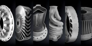
Technologies such as Laser Powder Bed Fusion (LPBF), Electron Beam Melting (EBM), Directed Energy Deposition (DED), and Binder Jetting have fundamentally altered mechanical design paradigms. By allowing the fabrication of geometries previously deemed impossible—such as conformal cooling channels, topology-optimized lattice structures, and consolidated multi-part assemblies—metal additive manufacturing offers unparalleled design flexibility and material efficiency, greatly improving the buy-to-fly ratio in aerospace applications.
       [Raw Metal Powder (15-63µm)]
                  │
                  ▼ (Thermal Fusion / Melting / Sintering)
       [As-Built Additive Part] ──► Extreme Roughness (6.0 - 50.0 µm Ra)
                  │
                  ▼ (Advanced Surface Finishing Bottleneck)
     ┌────────────┴────────────┐
     ▼                         ▼
[Functional Optimization]  [Fatigue Life Restoration] (Up to 800 MPa)
However, as industrial applications scale from proof-of-concept to full-rate production, a critical bottleneck has emerged at the intersection of part generation and functional deployment: surface finish and post-processing. Unlike conventional subtractive manufacturing processes, such as Computer Numerical Control (CNC) milling and turning, which inherently yield smooth, precision-machined surfaces, the layer-by-layer nature of metal additive manufacturing intrinsically produces rough, heavily textured exteriors and internal channels.
Industry data reveals that for metal additive systems, capital expenditure (CapEx) represents only 25% to 40% of the Total Cost of Ownership (TCO). Operating expenses (OpEx), including power, gas, and maintenance, account for 40% to 60%, while post-processing comprises a staggering 20% to 35% of total lifecycle costs. For B2B sectors with strict rules, the challenge in 2026 is no longer merely printing the part, but finishing it to strict aerospace and medical standards without destroying the economic viability of the additive process.
This detailed guide pulls together the latest 2026 market intelligence, metallurgical research, real-world B2B case studies sourced from professional networks such as LinkedIn, and raw practitioner sentiment from specialized forums like Reddit. This analysis gives a deep look at raw metal additive surface physics, the severe consequences for fatigue life, the suite of advanced post-processing technologies currently dominating the market, and the strategic realities faced by B2B buyers, procurement officers, and mechanical engineers operating on the modern shop floor.
2. The Fundamental Physics and Metallurgy of As-Built AM Surfaces
To understand why advanced finishing is a must, we have to look first at the metallurgical and physical mechanisms that set the raw condition of a metal 3D printed component. Roughness on these parts is not just a simple defect. It is the result of complex thermal, kinetic, and mechanical forces that occur during powder-bed and directed-energy processes.
Melt Pool Dynamics, Thermal Gradients, and Energy Density
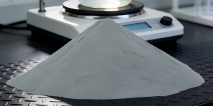
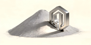
In Laser Powder Bed Fusion (LPBF) and Electron Beam Melting (EBM) processes, a high-powered thermal energy source traces the cross-section of a digital CAD model across a bed of fine metal powder, which typically ranges from 15 to 63 microns ($\mu\text{m}$) in diameter depending on the desired resolution and material. As the energy source melts the powder, a localized melt pool is formed.
The volumetric energy density applied to the powder bed controls how this melt pool behaves. The energy density ($E_v$) is a function of the laser power ($P$) in watts, the scan speed ($v$) of the laser, the hatch spacing ($h$) between laser passes, and the layer thickness ($t$):$$E_v = \frac{P}{v \cdot h \cdot t}$$
Localized melting reaches temperatures of $2500^\circ\text{C}$ to $3000^\circ\text{C}$. Because cooling rates can exceed one million Kelvin per second ($1,000,000\text{ K/s}$), the melt pool faces violent thermodynamic turbulence. These sharp temperature changes cause spatter, the ejection of molten droplets, and the vaporization of alloying elements.
The heat from the melt pool also spreads outward into the surrounding loose powder bed. Powder particles that sit directly next to the melt pool boundary end up partially sintered or fused to the outside of the solidifying component. This creates a granular, highly abrasive texture on the component’s outer skin. Scanning Electron Microscopy (SEM) of raw LPBF 316L stainless steel shows a surface entirely littered with these partially melted microparticles, which are structurally weak but firmly stuck to the substrate.
The Stair-Stepping Effect and Down-Skin Vulnerability
Because metal additive manufacturing constructs components in discrete horizontal layers—typically measuring between 20 to 60 microns in thickness—curved, spherical, or angled surfaces suffer from the geometric approximation known as the stair-stepping effect. This physical limitation creates pronounced, terraced ridges along any surface that is not perfectly vertical or horizontal.
       Stair-Stepping Effect (Angled CAD Profile)

       CAD Profile Line:   /
                         /
       Actual Print:    █▄
                          █▄
                            █▄   <-- Terraced Ridges
Roughness depends heavily on the build orientation and the angle of the surface relative to the build plate. Horizontal up-skin surfaces generally exhibit better finishes as they are melted directly atop solid layers.
But down-skin surfaces—the undersides of overhangs facing the build plate—suffer from the worst roughness and highest defect rates. When a laser melts a down-skin layer, the energy penetrates deeper because it is firing into loose powder rather than a solid heat sink. This leads to dross formation, excessive powder attachment, and severe dimensional inaccuracy. Consequently, surfaces built at shallow angles relative to the build plate require significantly more aggressive post-processing to achieve functional smoothness.
Comparative Baseline of As-Built Surface Roughness (Ra)
The quantitative measure of this surface texture is typically expressed as the Roughness Average ($R_a$). Standard CNC machining easily achieves $R_a$ values between $0.4\ \mu\text{m}$ and $1.6\ \mu\text{m}$, creating surfaces suitable for high-pressure seals and precision bearings. In stark contrast, the raw surface of a metal additive part is vastly inferior and varies heavily depending on the specific technology utilized.
| Manufacturing Technology | Typical As-Built Surface Roughness ($R_a$) | Primary Bonding Mechanism | Dimensional Accuracy | Post-Processing Reliance |
|---|---|---|---|---|
| CNC Milling (Subtractive) | $0.4\ \mu\text{m} – 1.6\ \mu\text{m}$ | Subtractive cutting | $\pm0.005\text{ mm}$ | Minimal |
| Metal Injection Molding (MIM) | $1.0\ \mu\text{m} – 3.0\ \mu\text{m}$ | Sintering inside mold | High | Low |
| Binder Jetting (Sintered) | $3.0\ \mu\text{m} – 6.0\ \mu\text{m}$ | Chemical binding & furnace sintering | Moderate (High shrinkage) | Moderate |
| Laser Powder Bed Fusion (LPBF) | $6.0\ \mu\text{m} – 15.0\ \mu\text{m}$ | Laser thermal fusion | High ($\pm0.1\text{ mm}$) | High |
| Electron Beam Melting (EBM) | $20.0\ \mu\text{m} – 35.0\ \mu\text{m}$ | Electron beam in vacuum | Moderate | Very High |
| Directed Energy Deposition (DED) | $25.0\ \mu\text{m} – 50.0\ \mu\text{m}+$ | Coaxial powder/wire feed | Low (Near-net shape) | Absolute |
Table 1: Comparative analysis of as-built surface roughness and process characteristics across various metal manufacturing technologies.
As demonstrated in Table 1, processes such as Electron Beam Melting (EBM) produce significantly rougher surfaces than Laser Powder Bed Fusion (LPBF), primarily due to the use of larger powder particles and a heavily heated powder bed, which encourages aggressive partial sintering across the entire build envelope.
Binder Jetting produces relatively smoother, matte finishes because it does not involve localized thermal melt pools during printing; however, it requires extensive secondary furnace sintering which induces significant volumetric shrinkage, presenting a different set of dimensional challenges for engineers. Directed Energy Deposition (DED), while capable of high deposition rates between 1 to 5 kilograms per hour ($\text{kg/h}$), produces extreme surface roughness and is generally reserved for near-net-shape forging replacements or the repair of existing aerospace components.
3. The Critical Link Between Surface Topography and Fatigue Life
In high-stress B2B applications—such as aerospace turbine blades, automotive drivetrain components, nuclear reactor components, and load-bearing orthopedic medical implants—the surface roughness of an additive part is not merely a cosmetic or aesthetic issue. It is the primary limiting factor for mechanical reliability and product liability. The deep effect of surface shape on the fatigue life of metal 3D printed parts is a central focus of metallurgical research and quality assurance protocols in 2026.
Fatigue failure occurs when a component is subjected to cyclical loading and unloading over time. Under these dynamic conditions, the deep valleys of a rough LPBF or EBM surface act as severe microscopic stress points. When dynamic bending or tensile stress is applied, these geometric valleys amplify the local stress far beyond the nominal load, initiating microcracks at the surface. Over millions of cycles, these microcracks propagate through the internal microstructure of the part, eventually leading to catastrophic, brittle failure with minimal prior indication.
       Fatigue Microcrack Initiation

       Cyclic Loading (Tensile / Bending Stress) <─── ───►
       ───────────────────────────────────────────────────
         Unprocessed Peak   /\      /\      /\
                           /  \    /  \    /  \
         Deep Valley      /    \  /    \  /    \
                         /      \/      \/      \
                                 ▲
                          [Stress Concentrator] ──► Crack Initiates!
Extensive studies on Ti-6Al-4V, a ubiquitous aerospace and medical titanium alloy, reveal that raw additive components suffer a drastic reduction in high-cycle fatigue life compared to their conventionally forged or machined counterparts. For instance, tests indicate that while a forged aluminum or titanium part might endure ten million ($10^7$) cycles at a specific stress amplitude, an untreated additive version will often fail well before that benchmark due to surface crack initiation. Anisotropic microstructures resulting from layer-by-layer directional cooling further exacerbate this vulnerability.
Historically, the industry relied on Hot Isostatic Pressing (HIP) to improve the mechanical properties of additive parts. HIP applies extreme heat and uniform isostatic gas pressure to fully solidify the part and drive out internal microporosity and voids. While HIP works well to close internal defects and achieve 99.9% density, metallurgical studies have conclusively proven that HIP alone cannot compensate for the detrimental effects of surface asperities.
To restore the fatigue limit of an additive part to the baseline of wrought material, the exterior surface roughness must be physically removed or chemically leveled. Research demonstrates that when raw LPBF Ti-6Al-4V samples are post-processed via precision machining or advanced surface polishing on top of a HIP treatment, their fatigue strength can increase from a baseline of approximately 50–200 MPa up to 800 MPa, directly rivaling conventionally forged materials. So, for highly loaded, critical hardware with strict safety rules, advanced post-processing is a must.
4. Real-World B2B Case Studies: Implementations and Validations
The theoretical capabilities of additive manufacturing and advanced finishing technologies are currently being validated across diverse B2B supply chains. Analysis of corporate announcements, industry reports, and validated professional case studies on platforms like LinkedIn reveals how industry leaders are systematically overcoming the surface finish bottleneck.
NASA Jet Propulsion Laboratory and REM Surface Engineering
To support the highly critical Mars Sample Return mission, NASA’s Jet Propulsion Laboratory (JPL) required the development of ultralight, crushable energy-absorbing lattice structures. These complex lattices were manufactured from A6061-RAM2 aluminum using additive technologies. Standard LPBF production left the intricate lattices with highly variable surface roughness and dangerous stress points. Conventional subtractive machining was physically impossible due to the delicate, cellular nature of the internal structure.
To resolve this, JPL partnered with REM Surface Engineering. By using REM’s Extreme ISF process—a highly controlled sequence of chemical polishing followed by chemical-mechanical polishing—the granular roughness and surface waviness of the aluminum lattices were entirely eliminated. Subsequent tensile and fatigue testing verified that the polished additive aluminum achieved significant, statistically verifiable increases in yield strength, ultimate tensile strength, and elongation compared to both the raw and standard grit-blasted baselines. This advanced finishing process ensured the critical reliability and predictable deformation of the hardware upon planetary impact.
Danish Technological Institute (DTI): Industrial Demonstrations
The Danish Technological Institute (DTI) has led multiple B2B demonstration projects to validate the commercial viability of metal additive manufacturing coupled with advanced post-processing. Working with the SME Heatflow, DTI successfully engineered and printed complex gas-to-gas heat exchangers where internal roughness was mitigated to meet strict fluid dynamic efficiency requirements. Similarly, for the company FLO2R, DTI printed components for gas analysis equipment used in cement kilns, where precise surface finishing reduced the need for system maintenance.
In the aerospace sector, DTI collaborated with the startup Airflight to optimize a drone wing bracket. Utilizing topological optimization and the design freedom of LPBF, the team reduced the bracket’s weight by 67%. The subsequent application of automated post-processing ensured the parts met the strict aerodynamic surface requirements and fatigue life necessary for commercial flight. Furthermore, DTI has used the Micro Machining Process (MMP)—a patented catalysis technology—to finish rapidly rotating turbine equipment and medical implants, achieving $R_a$ values below $0.08\ \mu\text{m}$ while maintaining complex geometries.
HP Metal Jet in Consumer Goods and Industrial Systems
HP’s Binder Jetting technology, known as HP Metal Jet, is widely used in areas requiring high-volume production where surface aesthetics and complex internal geometries are paramount. Roca Group, a global leader in bathroom fixtures, partnered with HP to produce customized metal faucet handles. These components feature intricate digital textures that cannot be traditionally cast or machined. Because the Binder Jetting process leaves a matte, slightly porous green-state surface prior to sintering, secondary polishing technologies were integrated into the production line to provide the necessary consumer-grade shine and corrosion resistance.
In industrial applications, FDX and GKN utilized HP Metal Jet to produce the OsciJet cleaning nozzle for automated car wash systems. The nozzle requires highly complex internal fluidic channels that create a specific oscillating spray pattern. This internal geometry is impossible to CNC machine, but easily printed and subsequently finished via abrasive fluid flow techniques, demonstrating the unique value proposition of additive manufacturing when paired with appropriate post-processing.
5. Raw Practitioner Sentiment: Insights from Reddit and Professional Forums
Talking to experienced CNC machinists, manufacturing engineers, and operators in 2026 shows a massive gap between sales hype and daily floor reality when producing certified metal parts.
The “Fancy Casting” Paradigm and the Subtractive Reality
A strong agreement among machinists is that metal 3D printing should not be viewed as a standalone replacement for precision machining, but rather as an incredibly advanced, digital casting process. Users frequently note that metal additive is ideal for producing geometries with internal cooling channels or consolidated assemblies that would otherwise require complex multi-part weldments.
However, practitioners are quick to highlight the physical limitations of the technology. As one highly upvoted engineer noted in a professional machining forum:
“There are a lot of physics barriers you run up against in the tech… they will always require machining or post-process on critical tolerance features.”
Machinists report that virtually every critical additive part they handle arrives on their desk with extra stock material specifically designed into the CAD model. This extra material is necessary so that the machinist can mill, turn, or grind the mating surfaces, bearing journals, and O-ring grooves down to functional tolerances. The raw printed surfaces are universally described as too rough and porous to act as a proper seal or dynamic joint.
Economic Constraints and the Illusion of “Desktop” Metal
While desktop polymer printing has been universally democratized, the B2B manufacturing sector remains highly skeptical of low-cost or “desktop” metal printing systems. Operators emphasize the severe safety hazards associated with handling reactive, highly combustible metal powders such as titanium, aluminum, and magnesium.
Practitioners note that a strict argon environment, industrial-grade air filtration, and specialized hazardous material training are non-negotiable requirements to prevent catastrophic fuel-air explosions on the shop floor.
Furthermore, engineering executives attempting to justify the massive capital expenditure of industrial additive systems (often ranging from $500,000 to over $1,500,000) point out that the technology lacks the traditional economy of scale found in injection molding, forging, or stamping. As a Chief Technology Officer of a metal printing startup observed on Reddit, the cost per unit in additive manufacturing remains highly linear. The technology is generally only financially viable for:
- “No other way to make it” geometries.
- Lightweight satellite and aerospace components where launch costs justify the premium.
- Situations where highly exotic materials (like Inconel or Titanium) would otherwise incur massive subtractive waste and tooling wear.
Dimensional Shrinkage, Anisotropy, and Material Handling
Engineers leveraging online B2B manufacturing services for aluminum and stainless steel parts frequently discuss pervasive issues with dimensional stability. While modern LPBF machines hold tolerances better than older generations, thermal warping, residual stress accumulation, and shrinkage remain acute problems during build cycles.
Users share extensive experiences of parts requiring mandatory stress-relief baking before they can even be safely cut off the build plate using Wire Electrical Discharge Machining (Wire EDM). The necessity of oversize printing to compensate for thermal contraction and the extensive post-processing requirements often lead to friction between design engineers and additive technicians.
6. Comprehensive Review of Advanced Surface Finishing Technologies
Because the industry knows surface finish is a bottleneck, the development of specialized post-processing gear has sped up. Adapting traditional finishing techniques to complex additive geometries is often impossible due to unreachable internal channels and delicate lattice structures. The 2026 market is dominated by sophisticated, automated technologies designed to penetrate intricate geometries while preserving strict dimensional tolerances.
                  Advanced Post-Processing Methods
                                 │
         ┌───────────────────────┼───────────────────────┐
         ▼                       ▼                       ▼
   [Mechanical]            [Chemical/Electro]        [Hybrid]
  - AFM (Internal)        - DLyte (Dry Electro)    - 5-Axis CNC
  - Centrifugal (Mass)    - Hirtisation            - HIP + Polishing
                          - ISF (Chem-Mech)
1. Abrasive Flow Machining (AFM)
Abrasive Flow Machining (AFM) has emerged as the premier mechanical solution for smoothing internal cavities, conformal cooling channels, and intersecting cross-holes that are utterly inaccessible to conventional tooling. The process utilizes a viscoelastic polymer medium heavily laden with abrasive particles (such as silicon carbide, aluminum oxide, or diamond). This semi-solid, putty-like medium is hydraulically forced through the internal passages of the 3D printed component in alternating directions.
As the viscoelastic fluid navigates the internal geometry, it acts as a flexible, intelligent file. The fluid dynamics of the process dictate that the media accelerates through narrow cross-sections and over restrictive surface peaks, thereby applying targeted cutting forces exactly where roughness is highest. AFM can reduce the internal surface roughness of LPBF printed heat exchangers or aerospace fuel manifolds from an as-built $R_a$ of $15\ \mu\text{m}$ down to an ultra-smooth $0.05\ \mu\text{m}$. By eliminating internal friction, boundary layer turbulence, and burrs, AFM directly enhances the thermofluidic efficiency of additively manufactured systems.
2. Isotropic Superfinishing (ISF) and Chemical-Mechanical Polishing
Developed by REM Surface Engineering, the Isotropic Superfinishing (ISF) process is a chemically accelerated vibratory finishing technique that has found immense traction in the additive sector, particularly for aerospace gears, power transmission components, and complex lattices. Unlike traditional abrasive tumbling, which can round sharp edges and fail to reach deep valleys, the ISF process utilizes a mild, alloy-specific acidic chemistry to create a soft conversion coating on the part’s surface.
The parts are placed in a vibratory tub containing high-density, non-abrasive ceramic media. The media easily wipes away the chemically softened peaks, leaving the valleys untouched. Because the chemical reaction is self-limiting and continuous, the process progressively levels the surface until a mirror-like, non-directional (isotropic) finish is achieved.
REM’s “Extreme ISF” variant was specifically tailored for metal additive manufacturing to combat the deep waviness and stubbornly adhered powder of LPBF and EBM parts. By removing surface defects, improving component cleanliness, and establishing a pristine texture, the ISF process greatly increases resistance to contact and bending fatigue.
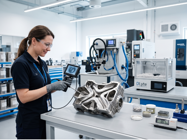
3. Dry Electropolishing (DLyte)
Traditional liquid electropolishing involves submerging a part (acting as an anode) into a highly acidic liquid electrolyte bath while applying an electric current to dissolve surface material. While successful, liquid baths can cause localized pitting, “orange-peel” effects, and require the expensive disposal of highly toxic wastewater.
To solve this, DLyte changed the industry by introducing “dry” electropolishing. Instead of a liquid bath, the DLyte system uses solid, macroreticular polymer spheres loaded with an electrolytic fluid. The metal 3D printed part is dragged and rotated through a bed of these conductive, solid particles. Ion transport occurs only where the solid particles make physical contact with the peaks of the part’s surface.
Because the solid media cannot reach into the microscopic valleys, material is exclusively removed from the asperities. This precise targeting reduces surface roughness by over 80% (achieving $R_a$ values under $0.01\ \mu\text{m}$) without rounding geometric edges, leaving negative surface skewness ($R_{sk} < 0$) which improves bearing ratios. In 2026, DLyte systems are standard equipment in B2B environments producing medical implants, dental prosthetics, and luxury consumer goods.
4. Chemical-Electrochemical Automated Finishing (Hirtisation)
The Hirtisation process, first developed by Hirtenberger Engineered Surfaces and now scaled globally by RENA Technologies, is a purely chemical-electrochemical solution tailored specifically for the automated post-processing of metal additive parts.
The technology functions entirely without mechanical abrasive media, making it perfectly suited for highly delicate, thin-walled structures and complex undercuts common in aerospace turbomachinery. The process is executed in three distinct modules:
- Step 1: Aggressively attacks the temporary AM support structures and caked-on powder, chemically dissolving them and reducing initial roughness from approximately $100\ \mu\text{m}$ to $10\ \mu\text{m}$.
- Step 2: Levels the surface down to an industrial standard of approximately $2\ \mu\text{m}$.
- Step 3 (Optional): Adds a decorative high-polish finish ($R_a < 0.5\ \mu\text{m}$).
Because it relies on hydrodynamic flow and electrochemical pulses, the treatment liquid penetrates every internal void, ensuring uniform material removal inside and out. Hirtisation significantly reduces the manual labor typically associated with breaking away support structures, offering a fully automated, scalable workflow for print farms.
5. Centrifugal and High-Energy Mass Finishing
For B2B operations focused on high-volume production of smaller, less delicate components, high-energy mass finishing remains a staple. Technologies such as centrifugal disc finishing and centrifugal barrel finishing use high rotational forces to increase the effective weight and cutting power of abrasive media.
These systems feature material removal rates up to ten times faster than standard vibratory tumbling. While highly efficient for deburring, radiusing, and basic surface smoothing, the aggressive nature of high-energy finishing means it is generally unsuitable for parts with fine external details, sharp cutting edges, or easily warped thin walls. Manufacturers must carefully weigh the speed of centrifugal finishing against the geometric degradation (edge rounding) that inherently accompanies the process.
6. Precision CNC Machining: The Hybrid Workflow
Despite the vast advancements in chemical and abrasive flow technologies, traditional subtractive CNC machining remains an absolute necessity for B2B applications requiring tight functional tolerances. As discussed, metal 3D printing is generally limited to volumetric tolerances that cannot satisfy aerospace sealing or bearing requirements.
Consequently, the standard B2B protocol in 2026 is the “Hybrid Workflow”. The component is additively manufactured to near-net shape—incorporating complex internal lattices and lightweighting topologies—but extra stock material is intentionally designed onto the mating surfaces. Following stress-relief heat treatment, support removal, and general surface smoothing, the part is mounted in a 5-axis CNC mill or precision surface grinder. Here, critical interfaces are machined down to strict tolerances ($\pm0.001\text{ mm}$), ensuring that the final component leverages both the geometric freedom of additive manufacturing and the absolute accuracy of subtractive finishing.
| Post-Processing Technology | Primary Mechanism | Best Suited For | Key Limitations |
|---|---|---|---|
| Abrasive Flow Machining (AFM) | Viscoelastic abrasive fluid | Internal cooling channels, cross-holes | Cannot correct external macro-geometry |
| Isotropic Superfinishing (ISF) | Chemically accelerated vibratory | Aerospace gears, lattices, fatigue improvement | Slower process, requires specific chemistry |
| Dry Electropolishing (DLyte) | Solid polymer electrolyte spheres | Dental, medical, delicate edges | Line-of-sight media contact required |
| Hirtisation (RENA) | Electrochemical fluid pulses | Turbomachinery, automated support removal | Involves aggressive chemical handling |
| High-Energy Centrifugal | High-G rotational abrasive media | High-volume small parts, deburring | Causes edge rounding and detail loss |
| 5-Axis CNC Machining | Subtractive cutting | Precision mating surfaces, threads | Cannot machine complex internal voids |
Table 2: Strategic comparison of advanced post-processing technologies for metal additive manufacturing in 2026.
7. Design for Additive Manufacturing (DfAM): Solving Roughness in CAD
The most cost-effective method for managing post-processing in 2026 is solving the problem before the printer is ever powered on. Design for Additive Manufacturing (DfAM) requires a major change for mechanical engineers transitioning from traditional drafting and subtractive CAD environments.
                          DfAM Geometric Optimization
            Traditional Circular Channel       Self-Supporting Teardrop
                        __─────__                        /\
                     _─           ─_                    /  \
                    /               \                  /    \
                    │   COLLAPSE!   │                 /      \
                    \ _           _ /                 \      /
                       ──_______──                     \____/
                     (Needs Supports)             (No Supports Needed)
Because down-skin surfaces (overhangs) suffer the most severe roughness and dross formation, engineers use DfAM principles to carefully plan the build orientation. By orienting the part so that critical surfaces build vertically or at steep angles (ideally above 45 degrees relative to the horizontal build plate), the reliance on support structures is minimized. Support structures are not merely a waste of expensive, gas-atomized metal powder; their removal requires intensive manual labor (utilizing bandsaws, pliers, and wire EDM) and leaves behind heavily scarred surfaces that demand aggressive, time-consuming grinding.
Advanced B2B operations now use AI-driven generative design and topology optimization software to create intrinsically “self-supporting” structures. Features like teardrop-shaped internal cooling channels (rather than perfectly circular ones) prevent the channel roof from collapsing during the print, entirely eliminating the need for internal supports that would be physically impossible to remove.
Furthermore, predictive simulation software is widely used to model thermal stresses and warping before printing. This allows engineers to pre-deform the CAD model to compensate for volumetric shrinkage and residual stress, reducing the failure rate and ensuring that the final part geometry matches perfectly with the intended post-machining toolpaths.
8. Economics and Supply Chain Realities for B2B Procurement
For B2B buyers and procurement officers in 2026, investing in metal additive manufacturing requires navigating a complex economic landscape. The decision to shift from traditional forging or casting to LPBF or Binder Jetting relies on a disciplined methodology that aligns capital investment with clear production outcomes.
Total Cost of Ownership (TCO) and ROI
Procurement teams must recognize that the sticker price of a metal 3D printer (ranging from $100,000 for entry-level systems to over $1,500,000 for multi-laser production platforms) is only the beginning. Operating expenses, including proprietary metal powders, high-purity argon gas, and specialized labor, dictate the ongoing unit economics.
Most importantly, buyers must map the entire post-processing chain prior to purchase. Integrating a printer without budgeting for a Wire EDM machine, a stress-relief furnace, Hot Isostatic Pressing (HIP) services, and precision finishing equipment (like AFM or DLyte) will result in a stranded asset capable only of producing rough, unusable blanks.
Return on Investment (ROI) rises quickly in specific scenarios:
- The production of highly complex, lightweight, high-value components.
- Low-volume, high-mix part runs where traditional tooling costs are prohibitive.
- The consolidation of massive, complex assemblies into single parts.
If a component requires thousands of units and features simple geometries, traditional forging or CNC machining will remain the economically dominant choice.
Regulatory Certification and Quality Assurance
In the aerospace, defense, and medical sectors, material certification and quality assurance are non-negotiable. Sourcing certified powder that complies with stringent standards (such as ASTM F3184 for 316L stainless steel) is crucial, as impurities or improper particle size distributions can lead to catastrophic failures under stress. US buyers navigating the defense sector must ensure ITAR compliance, while aerospace manufacturers require verified suppliers capable of meeting AS9100 and NADCAP certifications for heat treatment and HIP processes.
To guarantee lasting results, manufacturers rely on extensive non-destructive testing, including computed tomography (CT) scanning, to inspect internal channels for residual powder and microscopic voids. The 2026 supply chain favors integrated production hubs where printing, heat treatment, and surface finishing are housed under one roof, shortening lead times, reducing the risk of transport damage, and keeping a clear chain of custody for certified components.
9. FAQ: Expert Answers on 3D Metal Printing Surface Finish
Q1: Is metal 3D printing finally cost-effective enough to replace CNC machining for low-volume industrial parts?
No, traditional CNC machining remains far more cost-effective for simple geometries; metal printing is only viable for complex, consolidated, or ultra-lightweight designs.
B2B buyers must perform a holistic Total Cost of Ownership (TCO) analysis. Capital expenditure for the printer represents only 25% to 40% of the total cost; operating expenses (argon gas, proprietary powder, massive electricity draw) and intensive post-processing consume the majority of the budget. Metal printing becomes highly profitable only when organizations aggressively practice Design for Additive Manufacturing (DfAM).
This involves consolidating multi-part assemblies into a single print, topology optimizing aerospace components to drastically reduce weight, or utilizing internal conformal cooling channels that dramatically reduce cycle times for injection molding tools. For simple geometries, traditional CNC remains vastly superior in speed, surface quality, and unit economics.
Q2: How are manufacturers successfully smoothing the inside of complex conformal cooling channels if traditional polishing tools cannot reach them?
Manufacturers use fluid-based systems like Abrasive Flow Machining (AFM) or electrochemical Hirtisation to flush abrasive mixtures or liquid pulses through complex internal channels.
AFM utilizes a viscoelastic polymer putty mixed with abrasive grit, which is hydraulically forced through the internal passageways. The fluid dynamics naturally focus the cutting action on the roughest peaks and restrictive corners, reducing internal $R_a$ values from $15\ \mu\text{m}$ to under $0.1\ \mu\text{m}$ without altering the macro-geometry of the part.
For highly intricate turbomachinery or delicate lattices where hydraulic pressure might damage thin walls, chemical-electrochemical processes dissolve roughness via hydrodynamic flow and targeted voltage pulses, ensuring uniform internal polishing.
Q3: Does the rough surface finish of LPBF printed parts actually compromise their structural integrity in load-bearing applications?
Yes, rough raw surfaces act as microscopic stress points where cracks easily start, cutting a part’s fatigue life by up to 50% under cyclic loads.
In high-cycle fatigue environments (such as dynamic bending, vibration, or tensile loading), these surface defects serve as the primary initiation points for microcracks. This phenomenon can cut the fatigue life of high-strength alloys like Ti-6Al-4V by up to 50% compared to conventionally forged baselines.
Standard B2B protocol for flight-critical or medical hardware requires Hot Isostatic Pressing (HIP) to cure internal porosity, mandatorily coupled with aggressive surface polishing (like Isotropic Superfinishing) or precision CNC machining of the exterior to restore optimal fatigue resistance.
Q4: What are the true, reliable tolerances we can expect from a metal 3D printer without any secondary machining?
Raw prints generally hold tolerances of ±0.1 mm to ±0.3 mm, meaning you must design extra stock material (0.5 mm to 1.0 mm) and machine critical features later.
The inherent surface roughness (typically 5 to $15\ \mu\text{m}\ R_a$) dictates that creating airtight seals, precision bearing interfaces, or sliding mechanical fits directly off the printer is physically impossible. Furthermore, internal threads smaller than a specific diameter cannot be reliably printed and must be tapped post-build.
For precise mating surfaces, engineers must design the CAD model with 0.5 mm to 1.0 mm of extra stock material, which is subsequently milled, turned, or precision-ground down to strict aerospace tolerances ($\pm0.001\text{ mm}$).
Q5: For delicate, thin-walled medical and dental implants, how does dry electropolishing (DLyte) prevent the edge-rounding commonly caused by traditional tumbling?
DLyte uses solid polymer spheres instead of heavy ceramic media, removing metal ions only from microscopic surface peaks without blunting sharp corners or edges.
Traditional vibratory tumbling uses heavy media that aggressively attacks corners and sharp edges, leading to unacceptable geometric deformation and blunt profiles on delicate parts. In the DLyte system, material removal is driven purely by anodic oxidation (ion transport) occurring only at the exact points where the solid spheres touch the microscopic peaks of the metal surface, leaving the deep valleys and macro-edges untouched.
This selective process ensures that ultra-fine geometric details—such as the cutting edges of surgical tools or the precise fitment of dental partials—are perfectly preserved while simultaneously achieving a sub-$0.01\ \mu\text{m}\ R_a$ mirror finish.
10. Conclusion: Embracing the Complete Manufacturing Ecosystem
As the global B2B sector fully embraces metal additive manufacturing in 2026, the industrial narrative has firmly shifted from the novelty of the printer to the efficiency and reliability of the entire production ecosystem. Metal 3D printing is no longer viewed as a standalone, magic-bullet technology; it is the first, highly complex step in a multi-stage manufacturing chain.
The inherent physics of powder bed fusion and directed energy deposition guarantee that raw parts will suffer from severe surface roughness, partially fused particles, and residual thermal stresses. These defects act as critical stress points that violently degrade the fatigue life of load-bearing components. Therefore, surface finishing and post-processing are not aesthetic afterthoughts, but absolute mechanical prerequisites dictated by fracture mechanics and regulatory compliance.
The growth of advanced technologies—such as Abrasive Flow Machining for internal thermofluidic channels, Dry Electropolishing for delicate medical geometries, Hirtisation for automated support removal, and Isotropic Superfinishing for aerospace fatigue enhancement—has provided manufacturers with the precise tools necessary to overcome the surface finish bottleneck.
However, as echoed consistently by shop-floor practitioners, metal additive manufacturing remains a highly specialized “complex casting” process. It cannot entirely circumvent the need for precision CNC machining to achieve airtight seals, tapped threads, and strict geometric tolerances.
For B2B procurement and engineering teams, success dictates adopting a rigorous Total Cost of Ownership perspective. Capital investments must focus equally on downstream post-processing infrastructure as they do on the 3D printers themselves. By marrying disciplined Design for Additive Manufacturing (DfAM) principles with an automated, hybrid post-processing workflow, industrial manufacturers can finally unlock the true economic, structural, and geometric potential of metal 3D printing at full production scale.