




Back to 3D Printing in Aerospace
Author: Felix Lee
Position: CEO at Forgecise
Technical Reviewer:
Forgecise Engineering Team
Last Updated: August 2026
Table of Contents
Quick Answer: What Is Additive Manufacturing for Turbine Blades?
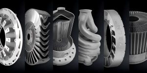
Additive manufacturing for turbine blades uses metal 3D printing technologies such as LPBF, EBM, and DED to create complex turbine components with advanced cooling designs, faster development cycles, and improved repair options. It will not fully replace traditional casting, but it is changing how aerospace and energy companies design and produce high-performance turbine parts.
TL;DR
- Turbine engines need higher temperatures to improve efficiency, but extreme heat pushes traditional materials to their limits.
- Additive manufacturing allows engineers to create cooling structures that traditional casting cannot produce.
- The main challenge for 3D printed turbine blades is not shape design but high-temperature material performance.
- Technologies such as Directional Recrystallization (DRX) are helping AM materials achieve better creep resistance.
- The future turbine industry will combine additive manufacturing with investment casting instead of replacing one with the other.
Additive Manufacturing for Turbine Blades: A New Direction for High-Temperature Engineering
Turbine blades operate in one of the most difficult environments created by modern engineering.
Inside aerospace engines and industrial gas turbines, blades face:
- extreme heat,
- strong centrifugal forces,
- oxidation,
- thermal cycling,
- long operating hours.
The demand for better fuel efficiency pushes manufacturers to increase turbine inlet temperature (TIT). A higher TIT allows engines to extract more energy from combustion gases.
A temperature increase of around 100°C can improve overall engine efficiency by roughly 2–3%.
But there is a problem.
The gas temperature around modern turbine sections can be higher than the melting point of the metals used to build the blades.
The blade survives because engineers combine:
- nickel-based superalloys,
- thermal barrier coatings,
- advanced cooling systems,
- precise manufacturing methods.
For decades, investment casting has been the main manufacturing method for turbine blades. It can produce directionally solidified (DS) and single-crystal (SX) structures that provide excellent resistance against high-temperature creep.
However, traditional casting has a major limitation.
The cooling design is restricted by what manufacturers can physically create and remove using ceramic cores.
This is where additive manufacturing changes the design process.
Instead of asking:
“Can this cooling channel be cast?”
Engineers can ask:
“How should the cooling system be designed for the best thermal performance?”
How Does Additive Manufacturing Improve Turbine Blade Cooling?
Additive manufacturing allows engineers to create internal cooling systems that are extremely difficult or impossible to manufacture using traditional casting.
Modern turbine cooling combines several methods:
- internal cooling channels,
- impingement cooling,
- film cooling,
- advanced lattice structures.
The goal is simple:
Remove heat from the blade while using the smallest possible amount of cooling air.
Cooling air comes from the compressor, and excessive cooling reduces engine efficiency.
From Serpentine Cooling to Gyroid Structures
Traditional turbine blades use serpentine cooling channels.
These channels contain internal features called rib turbulators or trip strips.
Their purpose is to disturb airflow and improve heat transfer.
However, these designs are limited by ceramic core manufacturing.
During investment casting, ceramic cores must survive:
- wax injection,
- high-temperature metal pouring,
- shell processing,
- chemical removal.
Very complex cores can break or become impossible to remove.
Additive manufacturing removes this limitation.
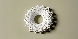
One promising approach is the use of gyroid cooling structures.
A gyroid is a type of Triply Periodic Minimal Surface (TPMS) structure.
It creates:
- large internal surface areas,
- continuous cooling paths,
- improved heat exchange,
- lightweight structures.
Research on AM-produced gyroid cooling channels has shown significant improvements compared with simple internal passages.
Some studies reported:
- heat transfer coefficient improvements of about 8.3 times,
- cooling range improvements of about 1.93 times.
The reason is the complex internal geometry.
The structure creates more turbulence, which helps mix cooler air with the hot boundary layer near the metal surface.
However, there is always a trade-off.
More turbulence improves cooling, but it also increases pressure loss.
Engineers must balance:
- cooling performance,
- airflow resistance,
- compressor energy loss.
Advanced models, including polynomial regression methods, have been used to predict the best lattice designs. Some models have achieved more than 96% prediction accuracy for selected cooling conditions.
How Do Film Cooling and Impingement Cooling Work with AM?
Internal cooling is only part of turbine blade protection.
Impingement Cooling
Impingement cooling uses high-speed air jets that hit internal blade surfaces.
It is especially important near the leading edge, where heat loads are extremely high.
Traditional manufacturing limits the shape and location of these internal cooling features.
Additive manufacturing allows more complex designs that can place cooling exactly where heat is concentrated.
Film Cooling
Film cooling creates a protective layer of cooler air over the outside of the blade.
Small holes release cooling air, creating a barrier between:
- hot combustion gases,
- the metal surface.
Traditional film cooling holes are usually produced through:
- laser drilling,
- electrical discharge machining (EDM).
These methods limit hole geometry.
Additive manufacturing allows:
- curved cooling outlets,
- complex hole shapes,
- conformal cooling paths.
This helps create a more stable cooling film and allows blades to operate at higher temperatures.
How Does Topology Optimization Improve Turbine Blade Design?
Additive manufacturing also changes how engineers think about blade structure.
Traditional manufacturing starts with a shape and removes material.
Topology optimization starts with performance requirements.
Computer algorithms analyze:
- mechanical loads,
- thermal conditions,
- rotational forces.
Then they remove material from low-stress areas while keeping strength where it matters.
Benefits include:
- lighter components,
- lower centrifugal stress,
- improved fatigue performance.
A small reduction in blade weight can reduce stress across the entire rotating system.
Why Are Materials Still the Biggest Challenge for 3D Printed Turbine Blades?
Additive manufacturing solves the geometry problem.
The harder problem is metallurgy.
A turbine blade is not just a shape.
Its internal crystal structure determines how long it survives.
At extreme temperatures, metals slowly deform under constant stress. This process is called creep.
For rotating turbine blades, creep resistance is critical because blades experience:
- continuous rotation,
- high temperature,
- long service periods.
Why Do Standard AM Turbine Blades Struggle at High Temperatures?
Traditional turbine blades use carefully controlled crystal structures.
The most advanced blades are often made using:
- directional solidification (DS),
- single-crystal (SX) casting.
These structures reduce grain boundaries, which are weak points during long-term high-temperature operation.
By comparison, common metal additive manufacturing processes such as:
- Laser Powder Bed Fusion (LPBF),
- Electron Beam Melting (EBM),
create parts through rapid melting and cooling.
The cooling rate in LPBF can reach approximately:
10⁵–10⁷ K/s
This rapid process creates a fine-grained, polycrystalline structure.
The benefits include:
- high strength,
- good fatigue performance,
- detailed geometries.
However, turbine environments are much more demanding.
At temperatures above 1,000°C, grain boundaries can become paths for:
- creep deformation,
- grain boundary sliding,
- crack growth.
This is why early AM turbine components were mainly used for:
- prototypes,
- lower-temperature parts,
- stationary components such as nozzle guide vanes (NGVs).
The industry needed a solution that could combine AM geometry with casting-level material performance.
How Does Directional Recrystallization Improve AM Turbine Materials?
Directional Recrystallization (DRX) is one of the most important developments in AM turbine metallurgy.
The goal is to transform the random grain structure of printed materials into a more controlled structure similar to directional solidification.
Researchers have tested DRX on nickel-based superalloys such as:
IN738LC
which is widely used in turbine applications.
The process uses controlled heating and movement to create a strong thermal gradient.
In experimental work:
- samples were heated to around 1,235°C,
- movement speed was controlled near 2.5 mm/hour.
This process encourages grain boundaries to move and replace small random grains with larger aligned columnar grains.
The result:
Before DRX:
- random grain orientation,
- many grain boundaries,
- weaker high-temperature creep performance.
After DRX:
- aligned grain structure,
- fewer harmful grain boundaries,
- improved creep resistance.
This technology creates a possible path toward AM turbine blades that combine:
- complex cooling designs,
- lightweight structures,
- improved high-temperature durability.
Researchers are also exploring functionally graded materials.
For example:
The blade root could use a structure designed for fatigue resistance, while the airfoil section could use a structure optimized for creep resistance.
Additive Manufacturing vs Investment Casting: Which Method Works Better?
The answer depends on the application.
Additive manufacturing and investment casting solve different problems.
The future turbine industry will likely use both.
Why Investment Casting Remains Important
Investment casting remains the preferred method for many commercial aircraft engine blades.
The process includes:
- Creating a wax pattern.
- Adding ceramic cores for cooling channels.
- Building ceramic shells.
- Removing wax.
- Pouring molten superalloy.
- Removing ceramic cores after cooling.
Its biggest advantages are:
Superior Material Performance
Investment casting supports:
- single-crystal alloys,
- directional structures,
- advanced superalloys.
These materials provide excellent resistance against:
- creep,
- thermal fatigue,
- long-term engine operation.
Large Production Economics
Once tooling is created, thousands of identical blades can be produced at lower unit cost.
For commercial aircraft engines requiring large production volumes, this remains a major advantage.
Where Does Additive Manufacturing Have the Advantage?
AM performs best when companies need:
- rapid development,
- complex designs,
- low-volume production,
- repair capability.
Advantages include:
No Traditional Tooling
A digital design change can move directly into production.
This reduces:
- tooling costs,
- development delays,
- supply-chain dependence.
Lower Material Waste
Traditional machining removes large amounts of expensive alloys.
AM uses only the material needed to build the component.
This is valuable when working with expensive turbine alloys such as:
- Inconel 718,
- Inconel 738LC,
- Rene 41.
Why Is Hybrid Manufacturing Becoming the Preferred Strategy?
Many aerospace companies are not choosing between AM and casting.
They are combining them.
The strategy is simple:
Use AM where it provides unique value.
Use casting where material performance and production volume matter most.
Siemens: 3D Printed Gas Turbine Blade Validation
A major industrial example involved:
- Siemens,
- Materials Solutions,
- EOS.
The companies developed fully 3D printed industrial gas turbine blades using metal additive manufacturing.
The blades used:
- nickel-based superalloy materials,
- LPBF manufacturing,
- advanced cooling designs.
The components were tested in a Siemens SGT-400 industrial gas turbine.
The blades operated under severe conditions:
- gas temperatures around 1,250°C,
- rotational speeds around 1,600 km/h,
- mechanical loads around 11 tons.
The project demonstrated that AM could move beyond laboratory testing and operate in real industrial turbine environments.
Honeywell: 3D Printed Ceramic Tooling for Faster Casting
Another important example is not printing the final metal blade.
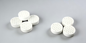
Instead, Honeywell used additive manufacturing to create advanced ceramic tooling and cores.
This approach keeps the benefits of investment casting while reducing development time.
Traditional tooling development could take:
1–2 years
Advanced printed ceramic tooling reduced early development timelines to approximately:
7–8 weeks
This shows how AM can improve traditional manufacturing instead of replacing it.
ORNL and WAAM: Large Turbine Blade Manufacturing
Large turbine components require different AM methods.
Wire Arc Additive Manufacturing (WAAM) uses:
- metal wire,
- electric arc energy,
- robotic deposition.
Compared with LPBF, WAAM is better suited for larger components.
A Siemens and Oak Ridge National Laboratory (ORNL) project demonstrated large steam turbine blade production using WAAM.
The project addressed supply-chain problems where large traditional castings could require very long lead times.
A full-scale turbine blade weighing more than 25 pounds was produced with:
- about 12 hours of printing,
- approximately two weeks total production time after machining.
Nikon: Additive Manufacturing for Turbine Repair
Turbine blades experience wear during operation.
Common damage includes:
- tip erosion,
- rubbing damage,
- surface degradation.
Traditional repair often requires skilled manual welding.
Modern DED repair combines:
- 3D scanning,
- digital comparison,
- automated laser deposition.
The workflow:
- Scan the damaged blade.
- Compare the shape with the original CAD model.
- Generate a repair path.
- Deposit new material.
- Machine the restored area.
This creates a faster and more repeatable repair process.
Does Surface Roughness Affect 3D Printed Turbine Blades?
Surface roughness creates both challenges and benefits.
The effect depends on where the roughness exists.
Internal Cooling Channel Roughness
Inside cooling channels, roughness can improve heat transfer.
It creates:
- more turbulence,
- stronger mixing,
- better cooling.
However, excessive roughness can also create:
- higher pressure loss,
- more compressor work,
- fatigue crack locations.
To manage this, manufacturers use:
- abrasive flow machining,
- chemical polishing,
- advanced internal finishing methods.
External Blade Surface Roughness
The external blade surface has different requirements.
Smooth surfaces improve:
- airflow,
- aerodynamic efficiency,
- thermal coating performance.
Modern turbine blades use coatings such as:
- Thermal Barrier Coatings (TBC),
- Environmental Barrier Coatings (EBC),
- Yttria-Stabilized Zirconia systems.
However, operating conditions quickly change the surface.
Blades experience:
- oxidation,
- hot corrosion,
- particle deposits,
- erosion.
Therefore, surface quality must be considered together with long-term operating conditions.
How Are AM Turbine Parts Certified for Aerospace Use?
Printing a turbine component is only the first step.
Aerospace companies require strict quality control because turbine blades are safety-critical parts.
Two major standards are:
- AS9100 Rev D
- NADCAP
AS9100 Additive Manufacturing Requirements
AS9100 requires full production control.
This includes:
Material Traceability
Companies must track:
- powder source,
- chemical composition,
- production history.
Process Control
Manufacturers must control:
- laser power,
- scan speed,
- layer thickness,
- chamber conditions.
The goal is consistency.
The first part and the thousandth part must meet the same requirements.
NADCAP Inspection Requirements
AM turbine parts require advanced testing.
CT Scanning
X-ray computed tomography checks:
- internal defects,
- trapped powder,
- porosity,
- cooling channel quality.
Hot Isostatic Pressing (HIP)
HIP reduces internal pores by applying:
- high pressure,
- high temperature,
- controlled atmosphere.
FPI and UT Testing
Fluorescent Penetrant Inspection detects surface cracks.
Ultrasonic Testing detects internal problems.
Only after completing these inspections can components move toward production approval.
Future of Additive Manufacturing for Turbine Blades
The future turbine industry will combine several technologies:
- additive manufacturing,
- advanced cooling design,
- improved superalloys,
- digital inspection,
- automated repair.
The biggest opportunity is not replacing every traditional process.
It is creating a smarter manufacturing system.
Traditional casting provides:
- proven materials,
- single-crystal performance,
- large-scale production.
Additive manufacturing provides:
- design freedom,
- faster development,
- complex cooling structures,
- repair solutions.
Together, they create a stronger path for future aerospace and energy systems.
Frequently Asked Questions
Can additive manufacturing replace traditional turbine blade casting?
Short answer:
No. Additive manufacturing and casting will continue to work together because they solve different engineering challenges.
Investment casting remains stronger for high-volume production and single-crystal blades. Additive manufacturing is better for complex cooling designs, prototypes, repairs, and specialized components.
Why are turbine blades difficult to manufacture?
Short answer:
Turbine blades operate under extreme heat, pressure, and mechanical loads that push materials close to their limits.
Manufacturers must balance temperature resistance, cooling performance, weight, and long-term durability.
What cooling methods are used in modern turbine blades?
Short answer:
Modern turbine blades use internal cooling channels, impingement cooling, and film cooling.
New additive manufacturing methods also enable advanced designs such as gyroid cooling structures and conformal cooling paths.
What materials are used for turbine blades?
Short answer:
Most advanced turbine blades use nickel-based superalloys because they maintain strength at very high temperatures.
Common materials include Inconel 718 and IN738LC.
Why are AS9100 and NADCAP important for AM turbine parts?
Short answer:
They verify that aerospace components are produced with strict quality control.
These systems require material tracking, process control, inspection, and documentation before parts can enter service.
Author
Felix Lee
CEO at Forgecise
Felix Lee works on advanced manufacturing strategy and industrial technology solutions. His focus includes how additive manufacturing can support aerospace, energy, and high-performance engineering applications.
Technical Reviewer
Forgecise Engineering Team
Reviewed for manufacturing accuracy, additive manufacturing terminology, and industrial application relevance.