




By Felix Lee, CEO at Forgecise — May 22, 2026
Table of Contents
Quick Summary (Direct Answer)
What is Computational Engineering Design in 3D Printing? Computational Engineering Design uses math functions and algorithms—rather than manual CAD drawing—to build 3D printing geometries. Engineers input physical boundary conditions like temperature limits, structural loads, and fluid rates. The code then generates the ideal shape automatically, allowing 3D printers to make complex internal features like seamless rocket cooling channels, microchannel cold plates, and medical implants.
Why Text and Diagrams Fail Advanced Additive Manufacturing
Yesterday, I published an article about generating heat sink geometries directly from code (“Radiator Design No Longer Requires CAD—Direct Computation via Code”). A few readers wrote back asking for hands-on details.
They were right. Text and static pictures cannot fully explain computational engineering.
Telling engineers to swap CAD software for code scripts sounds abstract. Throw in terms like Signed Distance Fields (SDF), Implicit Surfaces, or Voxel Grids, and it becomes hard to visualize what is actually happening behind the screen.
So, I built an interactive web app instead of writing another long text post. I went through five complete revisions in a few hours. Each tweak tied back to a practical problem in metal 3D printing. The result works as a practical mental model for computational thinking.
Placing Hardware in Real Physical Contexts
The breakthrough came in revision five when I set a strict rule:
Show every part inside its real operating environment, not as a standalone 3D shape.
Context matters more than polished visuals. When you see what a part is, where it sits, and how heat or load passes through it, you understand why specific parameters matter.
TRADITIONAL CAD:
[ Concept ] ---> [ Sketch in CAD ] ---> [ Run CAE Simulation ] ---> [ Redraw ]
* Geometry comes first | Physics is checked later

COMPUTATIONAL DESIGN:
[ Physics Constraints + Domain Rules ] ---> [ Run Code ] ---> [ Generated Shape ]
* Geometry comes last | Physics drives the shape
4 Practical Engineering Examples
Our web simulator features four key applications where metal additive manufacturing changes how we build hardware.
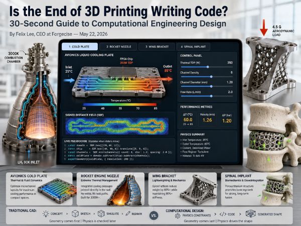
1. Avionics Liquid Cooling Plate (Thermal & Fluid Dynamics)
- The Problem: Electronics on aircraft run hot, but space and weight limits are tight. Every gram counts.
- The Simulation Setup:
- Displays a cross-section of an avionics cold plate.
- Top layer: High-power FPGA chip drawing 350W TDP.
- Liquid flow: Inlet on the left at 25°C, outlet on the right reaching 85°C.
- Green dashed lines show active fluid motion.
- Internal channel colors shift smoothly from cold blue to warm red.
- Live Indicators:
- Changing channel settings recalculates Temperature Rise ($\Delta T$), Flow Velocity ($v$), and Pressure Drop ($\Delta P$) instantly.
- Real-World Application: Metal 3D printing lets engineers pack tight microchannels inside liquid cold plates, far beyond what traditional CNC milling can cut.
2. Rocket Engine Nozzle (Extreme Thermal Management)
- The Problem: Rocket combustion chambers hit 3000K. Traditional cooling jackets need hundreds of welded tubes, creating hundreds of leak risks.
- The Simulation Setup:
- Shows a full hot-fire ignition sequence.
- Chamber inlet marked at 3000K alongside clear nozzle wall boundaries.
- Inner cavity glows with hot gas colors and an animated exhaust flame.
- Internal cooling passages appear as two stacked rows of moving blue dots inside the metal wall.
- Bottom indicator marks the $\text{LH}_2$ (Liquid Hydrogen) 90K Inlet.
- Live Indicators:
- Adjusting throat diameter changes exhaust flame width.
- Changing cooling passage counts adjusts how densely the blue channels cluster inside the wall.
- Real-World Application: Commercial space companies print rocket engine chambers in a single piece. Printing internal cooling channels directly in the wall eliminates weak weld seams.
3. Aerospace Wing Bracket with Gyroid Lattices (Lightweighting & Mechanics)
- The Problem: Traditional solid metal brackets add heavy dead weight to aircraft structures.
- The Simulation Setup:
- Models a titanium alloy (Ti-6Al-4V) wing bracket.
- Solid top and bottom plates contain standard bolt holes for mounting.
- Central core fills with a continuous Gyroid TPMS (Triply Periodic Minimal Surface) lattice.
- Red arrow at the top marks an aerodynamic load vector of 4.5 G.
- Live Indicators:
- Adjusting wall thickness and cell size reveals immediate strength trade-offs.
- Cuts weight by over 40% while keeping over 90% of original stiffness.
- Real-World Application: Gyroid lattices distribute stress evenly and print without internal support structures on Powder Bed Fusion (PBF) systems.
4. Cervical Spine Implant (C5-C6 Fusion Cage & Biomechanics)
- The Problem: Spinal cages need to fit patient bone shapes while keeping open pores so real bone can grow inside.
- The Simulation Setup:
- Shows a C5-C6 cervical spine fusion cage positioned between upper and lower vertebrae.
- A shape slider morphs the implant footprint from round to square, matching standard surgical setups.
- Green arrows indicate natural bone growth direction.
- Live Indicators:
- When Porosity exceeds 55% AND Pore Size exceeds 250 μm, the green arrows turn bright green, showing “Ideal Bone Ingrowth Conditions”.
- Below these thresholds, the status alerts “Insufficient Porosity or Pore Size”.
- Real-World Application: Electron Beam Melting (EBM) and Selective Laser Melting (SLM) print porous titanium cages that mimic natural bone structures.
Traditional CAD vs. Computational Engineering
| Metric | Traditional CAD | Code-Driven Computational Engineering |
|---|---|---|
| Shape Creation | Manual mouse clicks, sketches, booleans | Math formulas, SDFs, code functions |
| Complex Features | Slow performance or crashes with dense lattices | Handles millions of micro-features smoothly |
| Design Sequence | Draw shape $\rightarrow$ Test physics $\rightarrow$ Redraw | Set physics rules $\rightarrow$ Code $\rightarrow$ Resulting shape |
| System Context | Isolated 3D part file | Part shaped directly by active physics |
| File Output | Fixed STEP or STL meshes | Reusable, editable algorithms |
Understanding Computational Design Thinking
Building this tool highlighted a fundamental shift in how hardware gets made:
- Traditional Thinking (Pre-set Shapes): You sketch a shape in CAD, send it off to simulation software, check where it breaks, and manually tweak the lines. The shape comes first; performance checks come second.
- Computational Thinking (Calculated Shapes): You set your goals first. You input thermal limits, load forces, and volume boundaries as math rules. Then, your code calculates the shape.
The geometry becomes the natural result of your physics constraints.
You cannot learn this mindset just by reading papers. You need to adjust parameters yourself and watch how physics forces the shape to adapt.
Inside the Interactive Web Simulator
The web tool gives clear visual feedback across six main areas:
- Header Navigation: Four tabs to switch between the Cold Plate, Rocket Nozzle, Wing Bracket, and Spinal Implant.
- Main Display: Live physical view with real-time temperature, force arrows, and fluid motion.
- Distance Field View: A real-time Signed Distance Field (SDF) map under the main graphic.
- Key Numbers: Bright gold numerical readouts showing performance metrics.
- Control Panel: Sliders on the right side linked straight to the physics rules.
- Code Window: Live pseudocode at the bottom that updates as you move any slider.
+-------------------------------------------------------------------------------+
|  [Tab 1: Cold Plate]  [Tab 2: Rocket Nozzle]  [Tab 3: Bracket]  [Tab 4: Cage] |
+----------------------------------------------------+--------------------------+
|                                                    | CONTROL PANEL            |
|          PHYSICAL WORKING DIAGRAM                  |  - Thermal TDP: [ 350W ] |
|     (Real-time Temp, Flow Vectors, Load Arrows)    |  - Channel Density: ===o |
|                                                    |                          |
|                                                    | PERFORMANCE NUMBERS      |
|----------------------------------------------------|  [ 85°C Peak ] [ 1.2Bar] |
|          SIGNED DISTANCE FIELD (SDF) MAP           |                          |
+----------------------------------------------------+--------------------------+
|  LIVE PSEUDOCODE (Updates line by line when sliders move)                    |
|  > const coldPlate = SDF.box([100, 50, 10]).subtract(SDF.microchannels(8));  |
+-------------------------------------------------------------------------------+
Frequently Asked Questions (FAQ)
What is a Signed Distance Field (SDF) in 3D printing?
An SDF is a mathematical function that calculates the shortest distance from any point in space to the surface of a shape. It uses positive values outside the object, negative values inside, and zero on the boundary, allowing software to generate smooth complex lattices without heavy 3D mesh files.
Why is CAD becoming a bottleneck for additive manufacturing?
Traditional CAD handles simple solid surfaces well but struggles with millions of internal lattice struts or custom cooling channels. File sizes balloon quickly, and software stutters or crashes when modifying complex geometries.
How does code-driven design lower weight in aerospace parts?
Code fills functional spaces with repeating structural patterns like Gyroid lattices instead of solid metal blocks. The algorithm places material only where mechanical stress requires it, cutting weight by up to 40% while preserving structural strength.
Explore Our Lab Projects
This simulator belongs to an ongoing collection of interactive hardware tools hosted at our laboratory portal: amyidao.com/bslab.
Along with this session (built around concepts similar to the open-source PicoGK framework), you can try our other interactive tools:
- Moon Tower 3D Printing Game: A hands-on game exploring lunar habitat construction using local regolith.
- Interactive Industry Resume: A web-based profile built for Apple’s executive team showing additive manufacturing capabilities.
- NVIDIA GPU Cooling Simulation: An interactive module testing liquid cooling performance under heavy GPU thermal loads.
- 3D Printing for Young Students: Interactive science modules introducing additive manufacturing basics.
- Japan Additive Manufacturing Defense Map: A detailed structural breakdown of defense supply chains in additive manufacturing.
Try the Simulator
Some hardware concepts are much easier to understand when you tweak the parameters yourself.
Note: The simulator runs best on a desktop browser where you have full view of the controls, code window, and graphics.
[Open the Computational Engineering Design Simulator at amyidao.com/bslab]
Author Profile
Felix Lee is the CEO at Forgecise, where he focuses on software-driven hardware design and advanced metal 3D printing workflows.
References:
- AM易道 (2026). Radiator Design No Longer Requires CAD—Direct Computation via Code.
- Leap71 (2024). PicoGK: Open-Source Compact Kernel for Computational Engineering.