


- Author: Felix Lee, CEO at Forgecise
- Published: June 5, 2026
- Category: Additive Manufacturing, Design for Additive Manufacturing (DfAM), Industrial Engineering
- Estimated Read Time: 15 minutes
- Editorial Note: This technical guide helps hardware engineers, B2B procurement managers, and manufacturing specialists cut post-processing labor and improve structural strength in high-precision polymer and metal additive manufacturing.
Quick Summary (TL;DR )
Why can’t a 3D printer have floating layers?
In material extrusion (FDM/FFF) and vat photopolymerization (SLA/DLP), a “floating layer”—a horizontal layer initiated in mid-air without vertical support—cannot exist because of gravity, viscoelastic fluid dynamics, and thermodynamics. Extruded polymers in their molten state cannot establish a normal opposing force to counter gravitational pull, causing structural sagging. Without a solid underlying foundation, there is no surface to compress against to create the necessary “squish factor” for polymer chain diffusion (layer adhesion), and heat transfer is too slow to solidify the polymer before it fails under its own weight. Advanced algorithmic slicing (e.g., WaveOverhangs) and dual-material co-extrusion (e.g., PLA/PETG interfaces) provide state-of-the-art mitigation strategies for modern industrial operations.
I. Thermodynamic and Mechanical Principles of Layer-by-Layer Extrusion
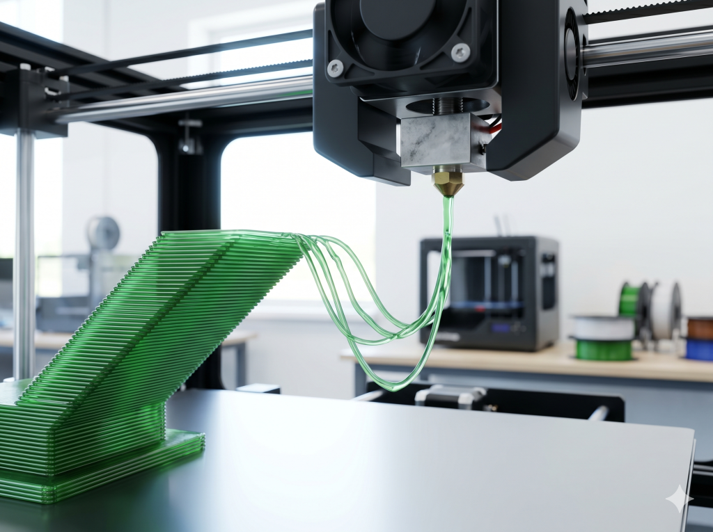
In Fused Deposition Modeling (FDM), you cannot print a “floating layer” in mid-air. This physical limitation comes down to gravity, viscoelastic fluid dynamics, and polymer thermodynamics.
FDM relies on slicing a 3D model into sequential horizontal planes. For any new polymer strand to stay where you want it, it must reach mechanical balance and solidify fast.
1. Viscoelastic Fluid Dynamics and the Force of Gravity
During extrusion, the solid polymer filament gets hot inside the print head. It passes its melting temperature () or glass transition temperature (
) and turns into a low-viscosity, semi-liquid state. When the nozzle deposits this molten bead, gravity pulls down on it constantly.
The gravitational force acting on a suspended filament segment of length
, density
, and cross-sectional area
is written as:
Here,
is the acceleration due to gravity (
).
If you do not have an underlying solid layer or a temporary support structure, there is no normal force () pushing back up. This lack of upward support means gravity pulls the hot polymer down. It droops, sags, or snaps, and the print fails.
[ Nozzle ]
|
v (Extruded Molten Bead)
~~~~~~~~~
/ \ <– Gravity (Fg) pulls the molten polymer downward
v v without an upward normal force to stop it.
2. The Mechanical Foundation: The “Squish Factor” and Layer Bonding
Layer bonding also relies on squeezing the hot polymer bead against the layer below it. Operators call this pressure the “squish factor.” This squeeze spreads the bead out, widening the contact area. With a wider contact area, the polymer chains can cross the boundary and build a strong cohesive bond.
The contact area for a layer height
and extrusion width
is calculated as:
Where
is the nozzle diameter. Without a solid foundation to press against, you cannot compress the polymer. This leaves the polymer chains unable to bind.
3. Heat Transfer Mechanisms: Conduction vs. Convection
Heat escape paths are also highly restricted. A solid underlying layer acts as a heat sink, quickly cooling the hot plastic through thermal conduction.
In contrast, a suspended strand must cool through natural or forced convection with the surrounding air. Convective cooling in air is a much slower process. Because the material stays hot and soft for too long, it stretches and breaks under its own weight.
II. Overhang Dynamics and the 45-Degree Rule
When prints transition from vertical to horizontal angles, they create overhangs. The standard 45-degree rule states that overhang angles of or less from the vertical axis usually print fine without support structures.
Vertical Axis
|
| / <– Overhang Angle <= 45° (Self-supporting)
| /
|/
[Solid Base]
At this threshold, the newly deposited layer maintains at least a 50% physical overlap with the layer below it. This overlap gives the polymer enough of a physical base and a conduction path to cool down before it can sag.
When the overhang angle goes past , the contact area shrinks rapidly, causing:
- Weak layer adhesion
- Split layers (delamination)
- Warped geometries
You can sometimes bridge short horizontal gaps between two solid points by turning up the cooling fans and slowing down the print speed. However, long gaps will always fail unless you use supports.
III. Cross-Technology Support and Anchoring Paradigms
The physical limits of printing unsupported layers change depending on your chosen 3D printing technology. Knowing these differences is vital for B2B clients who need to select the right process for complex industrial parts.
1. Material Extrusion (FDM/FFF)
FDM has the tightest limits regarding physical supports. Because the machine deposits melted plastics, it needs an underlying surface to resist gravity and establish the “squish” needed for strong bonds. Unsupported shapes must use sacrificial supports, which leads to extra waste and longer post-processing times.
2. Vat Photopolymerization (SLA/DLP)
SLA and DLP technologies cure liquid photopolymer resin using UV light. Liquid resin provides some buoyancy, but you still cannot print true “floating” layers or unanchored areas (called “islands”).
As the machine cures each layer against the bottom of the resin tank, the build plate moves up to peel the cured layer off the tank membrane. Unsupported islands cannot handle these mechanical peel forces (). They detach, warp, or stick to the bottom of the tank, causing print failures.
3. Powder Bed Fusion (SLS/MJF)
Selective Laser Sintering (SLS) and Multi Jet Fusion (MJF) are highly adaptable for complex shapes. These machines melt fine polymer powder layer by layer.
The loose, unsintered powder surrounding the part acts as a natural, dense support system. This means SLS and MJF can print complex overhangs, internal channels, and floating layers with no printed support structures at all. This removes the need for manual support removal.
4. Metal Powder Bed Fusion (SLM/DMLS)
Unlike polymer SLS, metal powder bed fusion needs robust, rigid support structures. Metal powder is not dense enough to hold heavy metal parts in place.
Additionally, the massive thermal gradients () and fast cooling rates in metal printing create intense internal residual stresses. Without rigid anchors holding the part to the build plate, these thermal forces make the metal layers warp and lift. The surrounding loose powder also has poor thermal conductivity compared to solid metal. Metal supports act as thermal heat sinks, pulling heat away from the melt pool to stop local boiling and warping.
5. Multi-Technology Comparative Matrix
The table below breaks down the limits, forces, and failures across these major processes:
| Technology / Process | Support Mechanism | Maximum Safe Overhang Angle | Dominant Forces and Stresses | Key Limitations and Failure Modes |
| FDM / FFF (Polymer) \ | Solid layer below or printed sacrificial support. | Gravity ( | Sagging, droop, loss of shape, weak layer bonds. | |
| SLA / DLP (Resin) \ | Structural anchors to the build plate. | Tensile peel forces ( | Island detachment, vat membrane sticking, warping. | |
| SLS / MJF (Powder) \ | Natural support from loose powder. | Recoater blade friction, cooling shrinkage. | Thermal curling, crystallization-induced shrinkage. | |
| SLM / DMLS (Metal) \ | Rigid anchor plates and thermal heat sinks. | Intense residual thermal stress, recoater impact. | Severe warping, cracks, recoater blade collisions. | |
| Multi-Layer UV Signage \ | Chemical bond to glass or acrylic. | Not applicable (2.5D printing). | Surface tension of liquid ink, UV shrinkage. | Misaligned layers, color bleeding, opacity failures. |
| Investment Casting \ | Plaster mold investment. | Not applicable (Liquid metal pour). | Hydrostatic pressure of liquid metal, cooling shrinkage. | Slag inclusion, cracked molds, surface nodules. |
IV. Industrial Homonyms in B2B Operations
In B2B industrial settings, the term “floating layer” can refer to other industrial processes beyond 3D printing:
- Industrial UV Signage Printing: In multi-layer UV LED printing (like Mimaki’s UCJV330-160), a “floating color layer” is a layer of color printed between black and white blockout layers. This creates “day-and-night” signs on windows . The graphic changes its look depending on whether there is light shining from behind it.
- Metal Casting and Pyrometallurgy: In lost-PLA casting, FDM prints serve as positive patterns burned out inside a plaster mold . During the melting and pouring of metals like aluminum or bronze, a “floating layer” of oxidized impurities (known as “dross” or “slag”) forms on top of the liquid metal inside the crucible. Workers must skim this layer off with a steel rod before pouring to keep structural defects out of the final casting.
V. Industrial Automation and Slicer-Side Mitigation Technologies
To run 3D printers on automated B2B production lines, engineering teams use smart slicing algorithms and multi-material setups to bypass the physical limits of unsupported layers.
1. The WaveOverhangs Slicer Algorithm
A recent open-source software option is the WaveOverhangs slicing algorithm, found in an experimental fork of OrcaSlicer. Standard slicers fill a layer using straight lines (like rectilinear or gyroid patterns) that require a physical layer underneath them. When these patterns meet an overhang, they usually fail without support structures.
In contrast, WaveOverhangs changes how the print head moves in the horizontal plane. The algorithm calculates curved, concentric toolpaths (wavefronts) that start from a solid, supported edge of the model and grow outward into the open air.
Normal Toolpath: WaveOverhangs Toolpath:
[====================] Void ( ( ( ( ( ( [Solid Edge] ) ) ) ) ) )
(Fails: No vertical backing) (Succeeds: Lateral self-anchoring)
As the print head moves over empty space, it lays down a bead that bonds sideways to the cooled, solid ring printed just before it in the same layer. This sideways bonding uses the material’s tensile strength and rapid cooling to successfully build horizontal overhangs up to without support structures underneath.
2. Incompatible Dual-Material Support Interfaces (PLA/PETG)
For industrial jobs that need smooth surfaces and tight tolerances on horizontal overhangs, multi-material systems (like automatic material changers) use incompatible plastics for support interfaces.
Because of differences in chemical polarity and molecular structures, Polylactic Acid (PLA) and Polyethylene Terephthalate Glycol (PETG) do not bond well when printed together. Slicing software uses this chemical incompatibility by:
- Generating standard, cheap support structures using the model’s main material (like PLA).
- Printing the final 2 to 3 “interface layers” directly beneath the model’s overhang surface using the incompatible material (like PETG).
This method allows the slicer to set the top Z-distance to exactly . The hot model material is compressed right onto the support interface, ensuring a flat, accurate first layer. Once finished, the PETG interface layer peels cleanly off the PLA part with very little effort. This leaves a smooth surface and removes the need for sanding or post-processing.
This dual-material technique is usually better than water-soluble filaments (like PVA or HIPS) in production shops. Soluble filaments absorb water quickly, need expensive dry boxes to stay usable, cost more, and make a lot of waste plastic (“purge poop”) during tool changes.
3. Dynamic Overhang Tuning Parameter Guide
The table below shows the key slicing settings needed to keep steep overhangs from sagging:
| Parameter | Recommended Standard Value | Dynamic Tuning Strategy | Impact on Overhang Integrity |
| Overhang Wall Speed | \ | Cut speed by 50-60% compared to standard inner walls. | Gives the extruded bead enough cooling and solidification time before the nozzle passes by again. |
| Extrusion Temperature | Lower end of material’s range (e.g., | Drop temperature by | Increases plastic thickness (viscosity) and limits structural sagging under gravity. |
| Layer Height | \ | Use variable layer height to make layers thinner in overhang zones. | Reduces the unsupported horizontal step size between consecutive layers. |
| Cooling Fan Speed | 100% (for PLA) | Turn auxiliary and part cooling fans up to maximum flow. | Speeds up the change from liquid to solid, locking the plastic shape in place. |
| Perimeters/Walls | perimeters | Set slicer to print walls from “Inner to Outer.” | Inner walls act as a physical anchor for the outer overhang lines. |
| Bridge Flow Rate | \ | Lower the extrusion multiplier slightly for bridging paths. | Stretches the hot strand slightly, keeping it tight to prevent gravitational sagging. |
VI. Prominent Professional Forum Case Studies and Authoritative Solutions
This section looks at the five most common problems with unsupported layers, homing errors, and support setups discussed on professional additive manufacturing forums, along with practical, shop-ready solutions.
Question 1: How can an engineering team resolve “floating” or “mid-air” support generation in modern slicers (Bambu Studio / OrcaSlicer)?
Short Answer: Reduce the support branch diameter to 1.0 mm and double the branch distance to at least 2.0 mm to stop nodes from overlapping on steep slopes.
Slicer Generation Error: Corrected Tree Supports:
[ Model Overhang ] [ Model Overhang ]
/ \ / \
(Floating) (Floating) (Trunks anchored to bed)
/ \ / \
[Build Plate] [Build Plate] [Build Plate] [Build Plate]
The Deep Dive: This error happens due to a math conflict between the slicer’s branch distance and branch diameter settings on angled walls. When the support branch diameter is too large compared to the branch distance, the mathematical nodes of neighboring tree branches overlap across different layers. On sloped or vertical surfaces, this overlap makes the software lose track of the support coordinates. It starts building branch roots in mid-air instead of anchoring them to the build plate or lower trunk structures.
Detailed Fix:
- Reduce Branch Diameter: Set the branch diameter to about
to stop node overlap on detailed shapes.
- Increase Branch Distance: Set the branch distance setting to at least twice the branch diameter (like
) to ensure plenty of space between support trunks.
- Switch Support Style: Change the support style to “Slim” or “Hybrid” and set the base pattern to “Rectilinear” with a spacing of
to keep the thin support walls stable during printing.
Question 2: Why do modern 3D printers with force-sensing nozzles (load cells) fail by homing in mid-air and executing “ghost prints”?
Short Answer: High filament tension or guide tube friction pulls up on the toolhead, triggering the load cell early before the nozzle touches the bed.
(Filament Tension / Drag Pulls Upward)
^
|
[ Tool Head / Load Cell ]
|
v (Homing downward)
=================== [ Build Plate ] ===================
The Deep Dive: Modern FDM printers (like the Prusa MK4 and Elegoo Centauri Carbon) use sensitive force-sensing load cells in the toolhead to detect when the nozzle touches the print bed. This gives the machine a perfect Z-offset. However, sometimes you get “ghost homing,” where the printer calibrates its Z-axis too high and starts printing in mid-air.
This failure comes from mechanical tension in the filament line. When using heavy filament spools (like 5 kg industrial spools) or if there is high friction inside the PTFE guide tubes, the extruder motor has to pull very hard to feed the plastic. This tension pulls up on the toolhead. During the downward homing move, this tension triggers the sensitive load cell early, tricking the printer into thinking it hit the bed when the nozzle is still hovering several millimeters in the air.
Detailed Fix:
- G-code Modification: Insert a retraction sequence into your start G-code (like retracting
of filament) right before the homing move. This pulls filament back from the hot melt zone and creates physical slack in the feed line.
- Reverse Bowden Installation: Install a fixed-length Bowden guide tube secured tightly between the printer frame and the extruder intake. This keeps feed forces from registering on the load cell during calibration.
Question 3: How can water-soluble supports be optimized in B2B production, and are there more cost-effective alternatives?
Short Answer: Use standard PLA for the bulk support structure and use incompatible PETG only for the final 2 to 3 interface layers.
PVA Soluble Support (AMS): Incompatible Material Interface:
[ PLA Model Layer ] [ PLA Model Layer ]
(Frequent tool changes) (2-layer PETG interface)
[ PVA Support Structure ] [ PLA Support Structure ]
(High waste and cost) (Low waste, snaps clean)
The Deep Dive: In automated manufacturing, changing materials on a single-nozzle printer requires purging the old plastic from the hotend to prevent mixing. This creates a lot of waste plastic (“purge poop”). Also, PVA is highly hygroscopic; if it absorbs damp air, it degrades, leading to failed extrusions and weak support structures.
Detailed Fix:
- Standardize Incompatible Support Interfaces: Print the main support structure using your primary material (like PLA) and use an incompatible material (like PETG) only for the final 2 to 3 interface layers.
- Minimize Tool Changes: This limits material changes to the transition layers right under the model’s surface, drastically cutting down on waste. The chemical differences between PLA and PETG allow the supports to snap clean off without leaving scars, offering a smooth finish for a fraction of the cost of soluble supports.
Question 4: How can the WaveOverhangs slicer algorithm be configured to achieve support-free 90-degree overhangs?
Short Answer: Set the wave perimeter extrusion width to 120-150% of the nozzle diameter, drop speed to 15-25 mm/s, and keep part cooling at 100%.
The Deep Dive: The WaveOverhangs algorithm (an experimental OrcaSlicer fork) lets you print horizontal overhangs up to without physical support structures. However, because it has no pre-built profiles, you have to calibrate the settings manually to make sure it works.
The tool generates curved, concentric paths (wavefronts) starting from a solid edge and moving out over open air. Each new ring must bond sideways to the cooled ring printed just before it in the same layer. If settings are wrong, the plastic loops will separate and drop into the void.
Detailed Fix:
- Calibrate Extrusion Width: Set the wave perimeter extrusion width to 120-150% of the nozzle diameter. This increases the sideways contact area between neighboring rings.
- Optimize Print Speed: Slow down the wave perimeters to
to give each ring enough time to cool and solidify before the next path passes.
- Configure Flow and Cooling: Turn the part cooling fan to 100% and adjust the flow rate to keep extrusion pressure steady. This stops the filament from dragging or pulling away from its anchor points.
Question 5: What are the most effective design and post-processing strategies to minimize support marks on functional B2B parts?
Short Answer: Place high-tolerance walls on the Z-axis, use a 100% dense interface, wait for complete cooling, and use a heat gun to fix stress marks.
The Deep Dive: In functional prototyping, post-processing steps like sanding and painting increase labor costs. When supports are unavoidable, you must use smart design and post-printing tricks to prevent surface damage. Standard support setups let hot plastic blend slightly with the support structure. When you tear the supports away, they break fibers on the model’s skin, leaving white stress marks or rough spots.
Detailed Fix:
- Design Optimization (DfAM): Orient your 3D models to place critical, high-tolerance walls on the Z-axis. Vertical walls naturally print with higher quality and do not need support structures.
- High Interface Density: If supports are necessary, set the support interface density to 100% with 2 to 3 interface layers. This spreads the model’s weight evenly, stopping local sagging and reducing surface marks.
- Controlled Post-Processing: Only pull supports off after the print has cooled completely to keep from warping the warm, soft plastic. Use specialized hand tools like needle-nose pliers, picks, or small wood chisels to pry supports away cleanly.
- Thermal Surface Reflowing: For PLA parts, pass a heat gun quickly over the surface (at about
to
). This melts the surface polymer slightly, hiding layer lines and removing the white stress marks left by the supports.
VII. Strategic Action Plan for B2B Rapid Prototyping and Production Integration
For B2B rapid prototyping shops and automated production lines looking to lower post-processing costs and boost print success rates, we recommend these strategic steps:
- Incorporate DfAM Guidelines in CAD Workflows: Set clear Design for Additive Manufacturing (DfAM) rules across your engineering teams. Use
chamfers, rounded fillets, and self-supporting teardrop shapes first for horizontal holes to reduce your overall need for supports.
- Implement Dual-Material Support Interfaces: For high-precision jobs, run incompatible material pairs (like PLA and PETG) on multi-nozzle or automated material changing machines. Set your support Z-gap to
to get smooth, accurate overhangs that snap apart without sanding.
- Upgrade Homing and Feed Path Hardware: On automated assembly lines, install fixed-length Bowden guide tubes and configure pre-homing retraction sequences in your G-code. This stops filament tension from triggering force-sensing load cells early, preventing mid-air “ghost printing” failures.
Deploy SLS or MJF for Complex Geometries: For high-volume production of parts with complex internal channels or thin features that are hard to support or clean, transition production from FDM to SLS or MJF powder-bed systems to take advantage of their self-supporting capabilities.