
- Author: Felix Lee, CEO at Forgecise
- Published: June 16, 2026
- Read Time: 15 mins
- Target Audience: B2B Procurement Managers, Manufacturing Engineers, R&D Leaders, Product Designers
Quick Verdict (The Executive Summary)
When comparing 3d print resin vs filament for industrial applications, the choice depends on your mechanical and geometric requirements. Filament-based Material Extrusion (FDM) is the best cost-effective choice for large, load-bearing parts requiring real thermoplastics with high tensile strength. Resin-based Vat Photopolymerization (SLA/DLP/MSLA) is required for highly complex, microfluidic, or visually critical parts that need extreme dimensional precision and a smooth surface finish.
Table of Contents
1. Introduction: The Industrial Shift in Polymer Additive Manufacturing
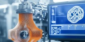
Additive manufacturing has transitioned from a rapid prototyping novelty into a critical, production-ready factory tool. Today, shop floors, research labs, and supply chains rely on polymer-based 3D printing to bypass traditional machining, reduce tooling lead times, and control operational costs.
For B2B procurement managers, engineers, and manufacturing leaders, choosing the right print system is a high-stakes decision. Selecting the wrong platform can cause structural failures under load, slow down cycle times, or waste capital budgets.
The market has two main polymer technology types:
- Material Extrusion, commonly called Fused Deposition Modeling (FDM) or Fused Filament Fabrication (FFF).
- Vat Photopolymerization, often grouped as resin-based printing, which includes Stereolithography (SLA), Digital Light Processing (DLP), and Masked Stereolithography (MSLA).
To make an informed choice, we must look at how these systems work, their material profiles, real-world case studies, and total costs.
2. Technology Breakdowns: Thermal Extrusion vs. Optical Photopolymerization
The divide between filament and resin systems starts at the point of layer deposition. This physical and chemical variance shapes the mechanical strength and visual quality of the finished part.
[FDM Mechanical Extrusion]
Thermoplastic Filament ──> Hot Nozzle (Melting) ──> Mechanical XY Deposition ──> Interlaminar Void Risk (Anisotropy)

[Vat Photopolymerization Optical Method]
Liquid Photopolymer ──> Selective UV Light Exposure ──> Chemical Cross-linking ──> Dense Matrix (Isotropy)
How Layer Formation Governs Mechanical Integrity
Material Extrusion (FDM / Filament)
FDM systems build parts mechanically. A solid thermoplastic filament is pushed into a heated printhead, melted, and continuously squeezed through a small nozzle. The printhead moves along the X and Y axes, laying down plastic lines onto a build platform that moves vertically.
As the hot plastic is laid down, it cools and solidifies. This rapid temperature drop creates internal stresses. The newly printed layer must melt the surface of the layer below it to form a solid bond. Because this bond is purely thermal and mechanical, it leaves tiny microscopic gaps.
This means FDM parts show anisotropic mechanical behavior. The strength across the vertical Z-axis is much weaker than the strength along the horizontal X-Y planes, making parts prone to splitting under load.
Vat Photopolymerization (SLA / DLP / MSLA / Resin)
Vat Photopolymerization uses liquid photocurable resins kept in a vat with a clear bottom window. An optical engine—either a scanning UV laser in classic SLA or a high-resolution monochrome LCD screen in MSLA—projects UV light upwards through the window.
This light triggers a rapid chemical reaction. The liquid monomers and oligomers bind together, cross-linking to form a solid polymer network.
Because this chemical bonding occurs dynamically across layer boundaries while the resin is still partially curing, the molecular bonds form a continuous matrix. This chemical process yields fully dense, isotropic mechanical properties with equal strength in all three directions ($X$, $Y$, and $Z$).
                Anisotropic (FDM)                     Isotropic (SLA/Resin)
             ┌──────────────────────┐               ┌──────────────────────┐
             │ ════════════════════ │               │                      │
   Z-Axis    │ ──────────────────── │ Interlaminar  │                      │ Continuous
  Weakness   │ ════════════════════ │ Void Lines    │                      │ Polymer
             │ ──────────────────── │               │                      │ Matrix
             └──────────────────────┘               └──────────────────────┘
Precision Boundaries: Resolution, Tolerances, and Surface Topography
FDM resolution is restricted by the physical size of the nozzle, which usually ranges from $0.2\text{ mm}$ to $0.8\text{ mm}$ in industrial settings. Thermal flow dynamics and plastic swelling as it leaves the nozzle prevent FDM systems from rendering tiny details. This leaves visible layer lines and a rough surface finish ($Ra > 15\ \mu\text{m}$).
Vat Photopolymerization resolution depends on optical limits, like the laser spot size in SLA or the pixel size of the LCD screen in MSLA. These light paths can focus down to $15\ \mu\text{m}$ to $50\ \mu\text{m}$.
This extreme precision allows resin printers to handle tiny details and achieve smooth surfaces directly from the build plate. Industrial SLA systems regularly hit surface roughness values ($Ra$) under $1.6\ \mu\text{m}$, which is perfect for aerodynamic or fluid flow testing.
Table 1: Tech Specs Comparison (FDM vs. Vat Photopolymerization)
| Performance Metric | Material Extrusion (FDM) | Vat Photopolymerization (SLA/DLP/MSLA) |
| Common Feedstocks | Thermoplastic Filaments (PLA, ABS, PETG, Nylon, PEEK, Ultem, PPS) | Thermoset Photopolymer Resins (Standard, Tough, Rigid, Biocompatible) |
| Typical Layer Height | $100\ \mu\text{m}$ to $300\ \mu\text{m}$ ($0.1\text{ mm} – 0.3\text{ mm}$) | $10\ \mu\text{m}$ to $100\ \mu\text{m}$ ($0.01\text{ mm} – 0.1\text{ mm}$) |
| XY Dimensional Tolerance | $\pm 0.3\text{ mm}$ to $\pm 0.5\text{ mm}$ | $\pm 0.1\text{ mm}$ to $\pm 0.2\text{ mm}$ |
| Surface Roughness ($Ra$) | High ($> 15\ \mu\text{m}$; prominent layer lines) | Low ($< 10\ \mu\text{m}$, down to $1.6\ \mu\text{m}$) |
| Mechanical Isotropy | Highly Anisotropic (weak vertical Z-axis bonding) | Isotropic (consistent strength in all directions) |
| Geometric Complexity | High (limited by support marks & gravity) | Superior (great for complex internal channels & microfluidics) |
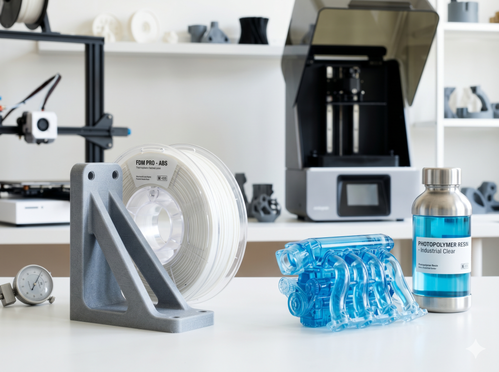
3. Material Science: Thermoplastics vs. Thermosets in Engineering
Choosing between FDM and resin systems means choosing between two different classes of polymers: thermoplastics and thermosets.
FDM Material Ecosystem: Production-Grade Thermoplastics
The primary benefit of FDM systems is their compatibility with production-grade engineering thermoplastics. This lets B2B users prototype and print parts using the same chemical options used in traditional injection molding.
- Standard Materials: PLA and PETG offer reliable tensile strength and print easily for quick concept models.
- Engineering-Grade Styrenes: ABS and ASA provide higher thermal stability and excellent UV resistance for outdoor parts.
- High-Performance Composites: For aerospace, automotive, and defense environments under high thermal and mechanical stress, FDM platforms use carbon-fiber-reinforced composites, Polyether Ether Ketone (PEEK), Polyetherimide (Ultem), and Polyphenylene Sulfide (PPS).
[Thermoplastics (FDM)] ──> Linear/branched polymer chains ──> Recyclable, meltable, high impact ductility
[Thermosets (Resin)]    ──> Chemically cross-linked networks ──> Infusible, rigid, high thermal stability (highly brittle)
Maximizing FDM Performance via Computational Modeling (PSO-ANN)
The mechanical performance of carbon-fiber-filled FDM filaments can be improved by optimizing software slicer parameters. A study on carbon-fiber-reinforced Acrylonitrile Butadiene Styrene (CF-ABS) printed on a Stratasys F170 system used a hybrid particle swarm optimization-artificial neural network (PSO-ANN) model to optimize variables.
The research analyzed three critical FDM processing inputs: slice height, infill density, and shell thickness.
[Optimization Input Variables]
├── Slice Height (Resolution)
├── Infill Density (Percentage)
└── Shell Thickness (Wall Count)
        │
        ▼ (Hybrid PSO-ANN Model Engine)
        │
[Optimized Mechanical Output]
├── Tensile Strength: Boosted from 0.038 to 0.042 kN/mm²
└── Volumetric Wear Rate: Minimized to 0.004605 mm³/m
The baseline tensile strength of the CF-ABS was $0.038\text{ kN/mm}^2$ under standard configurations. However, by tuning the variables to a slice height of 0.01 inches, an infill density of 66.6%, and a thin shell thickness of 0.06 mm, the predictive PSO-ANN model successfully:
- Increased the structural tensile strength to $0.042\text{ kN/mm}^2$.
- Minimized the material’s volumetric wear rate to $0.004605\text{ mm}^3/\text{m}$.
This study proves that computational optimization can reduce the mechanical weaknesses inherent in extrusion processes.
Resin Material Ecosystem: Cured Thermoset Networks
Vat Photopolymerization materials consist of liquid thermosetting monomers and oligomers that form rigid cross-linked chemical networks when exposed to UV light.
While standard resin formulations can be brittle, the industrial B2B ecosystem has introduced high-performance options:
- Tough/Durable Formulations: Resins blended with flexible monomers simulate the behavior of ABS or Polyurethane (PU), offering high elongation at break and better impact absorption.
- High-Temperature Resins: Formulated to withstand intense thermal stress, these materials support high heat deflection temperatures (HDT) for under-the-hood automotive testing or plastic injection mold cores.
- Biocompatible Formulations: Specialty medical and dental resins are certified for temporary or long-term clinical contact, driving the production of custom surgical guides and dental aligners.
Industrial Limitations of Resins
Despite these material developments, thermoset photopolymers have a few key vulnerabilities:
- Creep Degradation: Resins are prone to slow mechanical deformation (creep) when placed under continuous loads over time.
- UV Degradation: Ambient solar UV radiation continues the curing process of finished parts, eventually causing them to yellow, embrittle, and crack.
- Consumable Overhead: The chemical printing process degrades machine parts. Solvents and UV lasers cloud the optical window of the resin vat over time, requiring routine replacement of FEP/nFEP films and LCD screens to avoid print failures.
Table 2: Material Properties Comparison (FDM Thermoplastics vs. Resin Thermosets)
| Material Property | FDM Engineering Thermoplastics (e.g., Nylon-CF, PEEK, Ultem) | Vat Photopolymer Resins (e.g., Engineering Tough, Rigid) |
| Tensile Strength | Very High ($50\text{ MPa} – 100\text{ MPa}$ depending on printing orientation) | High to Medium ($40\text{ MPa} – 75\text{ MPa}$) |
| Impact Resistance | Outstanding (high toughness, energy absorption, and ductility) | Low to Medium (highly rigid structures are prone to brittle fracture under shock) |
| Material Creep | Low (highly resistant under sustained structural load) | Medium to High (exhibits progressive deformation over time) |
| Environmental Stability | High (ASA and specialty formulations strongly resist UV and weathering) | Poor (susceptible to yellowing and embrittlement under sunlight) |
| Biocompatibility | Limited (restricted to specialized medical-grade filaments) | Broad (widely certified Class I and IIa dental and surgical resins) |
4. Real-World Enterprise Case Studies: FDM and SLA in Action
To understand the business value of these technologies, we can look at how major automotive manufacturers and suppliers use FDM and Vat Photopolymerization in their workflows.
       [B2B Additive Value Proposition]
  ┌─────────────────────────────────────────┐
  │   Reliability                           │
  │ + Repeatability    ===>  Optimized ROI   │
  │ + Compliance            & Low Lead Times│
  └─────────────────────────────────────────┘
Automotive Tooling & Assembly: FDM Case Studies
Toyota Production Engineering
Toyota Production Engineering has integrated industrial FDM platforms directly into its automotive assembly plants to manufacture lightweight, functional tooling. During new model rollouts, assembly lines require custom jigs, positioning templates, and ergonomic worker aids.
By using engineering-grade ASA and Nylon 12 Carbon Fiber (PA12-CF) processed through GrabCAD Print software, Toyota bypasses traditional CNC machining of heavy steel fixtures. This on-demand tooling process reduces lead times and lowers tool weight, preventing strain and injuries for assembly workers.
Rapid Design Validation & Calibration: SLA Case Studies
Ford Motor Company
At Ford’s Rapid Technology Center in Merkenich, Germany, additive manufacturing specialists use high-speed SLA and MSLA platforms to compress vehicle design cycles. During the development of the Ford Puma, designers used professional Formlabs SLA printers to produce highly detailed, aesthetic prototypes of the vehicle’s rear lettering in a matter of hours.
Because the optical system of the resin printer eliminates visible layer lines, designers could evaluate how the physical text contours reflect and refract light under various lighting conditions—an assessment that cannot be replicated digitally.
[Formlabs SLA Printer] ──> Puma Rear Lettering Prototype ──> Smooth Ra < 1.6μm ──> Instant Light Reflection Analysis
Brose Group
Global Tier-1 automotive supplier Brose Group uses large-format SLA systems (such as the Formlabs Form 4L) to print rigid, durable setup parts for automated robotic weld cells. This allows welding technicians to physically calibrate and program robotic weld paths hours before the actual stamped sheet metal components are manufactured and delivered, eliminating robotic downtime.
Toyota Industries Corporation
Toyota Industries Corporation uses selective laser sintering (SLS) systems alongside industrial-grade SLA/DLP photopolymerization to evaluate complex internal engine and compressor components. For complex motor components requiring intricate copper coil windings, they use supportless SLS Nylon-12 prints. Concurrently, they leverage high-accuracy SLA resin molds to cast metal and polyurethane prototypes for advanced fluid and air flow tests.
Supply Chain Compression: Mid-Scale Manufacturing
Midwest Automotive Component Supplier
In the industrial supply chain, a major automotive component supplier in the American Midwest used large-scale SLA systems to fabricate visual prototypes and fit-check models for HVAC duct networks and interior dashboard trim. By transitioning from traditional tool-and-die prototyping to large-format resin printers, the supplier compressed its component verification testing cycle from six weeks down to nine days. This acceleration saved thousands of dollars in tooling modifications and secured rapid client approval.
Table 3: B2B Enterprise Value Matrix
| Enterprise | Primary Technology | Material Employed | Operational Outcome |
| Toyota Tooling | Industrial FDM | ASA, PA12-CF, Ultem | Rapid fabrication of lightweight, ergonomic assembly jigs and templates. |
| Ford Design | Professional SLA | High-Detail Resin | Same-day physical lettering prototypes to evaluate light and shadow reflections. |
| Brose Robotics | Large-Format SLA (Form 4L) | Fast Model & Rigid Resins | Immediate robot calibration for weld cells prior to sheet metal stamping. |
| Toyota Industries | SLA / DLP & SLS | SLA Castable Resin, SLS Nylon-12 | Combined SLS models for structural winding and SLA resin molds for fluid dynamic testing. |
| Midwest Supplier | Large-Scale Industrial SLA | Optical Clear / ABS-Like Resin | Compressed HVAC and dashboard prototype verification cycles from 6 weeks to 9 days. |
5. Economic Analysis: Total Cost of Ownership (TCO) in B2B Procurement
For corporate procurement, evaluating additive manufacturing requires a complete Total Cost of Ownership (TCO) analysis, weighing capital expenditure (CapEx) against ongoing operational expenditure (OpEx).$$\text{TCO} = \text{CapEx (Hardware \& Installation)} + \text{OpEx (Feedstocks + Consumables + Labor + Failed Prints Waste)}$$
Capital Expenditure (CapEx) Breakdown
The initial CapEx of industrial-grade Vat Photopolymerization is higher than that of Material Extrusion.
- FDM Systems: Professional FDM platforms range from $2,500 to $60,000. They have minimal facility requirements and can operate safely in standard ventilated office environments.
- Resin Systems: A certified, industrial-grade SLA system ranges from $15,000 to over $150,000. Additionally, resin setups require dedicated facility upgrades, including isolated HVAC venting, chemical wash stations, and hazardous waste disposal systems.
[FDM Workstation Setup]
FDM Printer ──> Simple Support Removal (Lower CapEx, Minimal Facility Overhead)

[Resin Wet Lab Setup]
Resin Printer ──> IPA Solvent Wash Tank ──> UV Curing Chamber (Higher CapEx, Dedicated HVAC Ventilation)
Operational Expenditure (OpEx) Analysis
The ongoing OpEx of resin printing is also typically higher.
- Feedstock Cost: Standard filaments cost a fraction of the price of equivalent engineering resins. Engineering filament ranges from $50 to $150/kg, while engineering resin costs $80 to $300/Liter.
- Consumables Overhead: Resin platforms incur ongoing costs for solvents (IPA), protective gear, replacement vat release films, and LCD masking screens.
- Labor Costs: FDM requires manual support removal, taking 30 to 60 minutes per part. Resin printing requires chemical washing and UV post-curing, but this is often automated, taking 15 to 25 minutes of hands-on labor.
Production Efficiency & Batch Optimization
Resin systems offer an efficiency advantage in high-density batch production. Because the optical engine cures entire layers simultaneously (whether via a laser scan or LCD projection), packing the build plate with dozens of small parts does not significantly increase print times, reducing the labor and machine cost per unit.
Table 4: CapEx & OpEx Cost Matrix
| Cost Component | Material Extrusion (FDM) | Vat Photopolymerization (SLA/DLP/MSLA) |
| Typical Machine CapEx | $2,500 – $60,000 | $15,000 – $150,000+ |
| Feedstock Material Cost | $50 – $150 / kg (Engineering Grade) | $80 – $300 / Liter (Engineering Grade) |
| Auxiliary Consumables | Nozzles, adhesive sheets, build plates | FEP/nFEP films, LCD screens, IPA, nitrile gloves |
| First-Print Success Rate | 75% – 85% (due to support failures and warping) | 92% – 96% (high stability on calibrated systems) |
| Post-Processing Labor | 30 – 60 minutes (manual support removal) | 15 – 25 minutes (automated wash, dry, and post-cure) |
| Workspace Footprint | Small (operates safely in ventilated offices) | High (requires a dedicated chemical wet lab and ventilation) |
6. Technical Forums Intelligence: High-Frequency B2B Q&As (FAQ)
Q1: Is it acceptable to leave liquid photopolymer resin in the printer vat overnight or during sleep, and will it solidify or degrade?
Short Answer: Yes, resin can stay in the vat for months if you keep the UV cover on and stir it before your next print.
Full Explanation: Liquid photopolymer resin is formulated to react strictly to specific UV light spectrums (typically $385\text{ nm}$ to $405\text{ nm}$). As long as the printer’s UV-blocking protective cover is securely in place and the machine is shielded from direct sunlight or heavy ambient fluorescent light, the resin will remain stable and liquid inside the vat for months.
However, operators must manage two critical issues before starting subsequent print runs:
- Pigment and Chemical Separation: Resins are complex colloidal suspensions of monomers, photoinitiators, and heavy organic pigments. Over extended idle periods, these heavy pigments sink to the bottom of the vat, forming a dense, separated layer. Initiating a print in this state will cause severe layer adhesion failures, blurry details, or uncured zones. Operators must use a soft silicone or plastic spatula to gently stir the resin in the vat before printing, ensuring they do not scratch or puncture the delicate FEP/nFEP release film at the bottom.
- Toxic Off-Gassing: Liquid resins continuously emit volatile organic compounds (VOCs) even when static. Leaving a resin printer idle with an uncovered vat is hazardous unless the system is situated in an isolated, dedicated laboratory room with continuous negative-pressure ventilation ducting to the outside.
Q2: Are resin printers still necessary in modern B2B workflows given recent high-resolution FDM updates?
Short Answer: Yes, because FDM cannot physically match resin’s sub-50-micron detail, smooth finishes, or isotropic strength.
Full Explanation: Modern high-speed FDM systems utilizing input shaping, active vibration compensation, ultra-fine $0.2\text{ mm}$ nozzles, and advanced multi-material systems (such as AMS units with water-soluble support interfaces) have significantly improved filament print quality. These advanced FDM printers can successfully print detailed visual models.
However, FDM is fundamentally restricted by the physics of thermal material extrusion.
The minimum feature size of FDM is limited by the diameter of the extruded molten plastic bead, which cannot achieve the sub-50-micron details of optical resin curing. Furthermore, FDM cannot resolve micro-overhangs or delicate, narrow geometric features (like thin prongs or fluid channels) without generating extensive mechanical support structures. These supports leave cosmetic scars on the model, requiring labor-intensive manual sanding and finishing.
For applications that demand tight dimensional tolerances (such as dental aligner models, fluidic manifolds, or high-accuracy connector housings), Vat Photopolymerization is a physical necessity.
Q3: How can operators maximize the surface quality and aesthetic finish of FDM prints to emulate the appearance of resin?
Short Answer: You can swap to a 0.2mm nozzle, lower layer heights to 0.06mm, turn on “ironing” in your slicer, or use acetone vapor for ABS/ASA.
Full Explanation: To minimize the visible layer lines inherent to material extrusion and emulate the smooth appearance of resin, operators can apply specific hardware and software slicing configurations:
- Aperture Reduction and Dynamic Layering: The primary mechanical bottleneck is the extruder nozzle. Operators should swap the standard $0.4\text{ mm}$ brass nozzle for a premium $0.2\text{ mm}$ hardened steel nozzle. In the slicing software (such as PrusaSlicer or OrcaSlicer), the layer height should be reduced to its minimum physical limit, typically $0.06\text{ mm}$ to $0.08\text{ mm}$, and variable layer height settings should be enabled to automatically thin the layers on curved top surfaces.
- Surface Ironing and Toolpath Optimization: Slicers can be configured to enable “ironing,” a post-layer pass where the hot nozzle lightly glides across the top flat surfaces without extruding filament. This melts down microscopic ridges and creates a matte, uniform finish.
- Chemical Post-Processing: For materials like ABS or ASA, exposing the finished part to an acetone vapor bath dissolves the outer polymer boundary, blending the layer lines into a glossy, injection-molded appearance.
Despite these optimization steps, FDM cannot physically match the isotropic micro-detail of resin due to the physics of extruded molten polymer flow.
Q4: Can FDM slice profiles utilize resin-style support structures to prevent ‘spaghetti monster’ print failures?
Short Answer: No, FDM parts need thick compressive supports (like trees or grids) because they must withstand the heavy physical force of a moving printhead.
Full Explanation: Slicing models with thin, branching, resin-optimized support structures on an FDM printer is a major cause of total print failures, often resulting in detached models and tangled filament nests.
The mechanical forces involved in each process are fundamentally different:
- Resin Support Dynamics: Resin supports are designed under the assumption of tensile gravity forces and light peeling suction in a liquid vat. They use extremely thin, delicate contact points (often less than $0.3\text{ mm}$ in diameter) designed to snap off cleanly.
- FDM Support Dynamics: FDM printing involves a heavy, fast-moving physical printhead that deposits molten plastic on top of the model. This extrusion process exerts dynamic shear forces and mechanical vibrations on the print. Thin resin-style supports lack the compressive strength to withstand these forces and will buckle, shear, or fail to adhere to the build platform.
Operators must load the raw, unsupported model into an FDM-specific slicer and generate thick, compressive support structures (such as organic tree supports or grid supports) designed to withstand the physical forces of the moving extruder.
Q5: Is it feasible to combine a resin-printed body and an FDM-printed head or mating component in a hybrid assembly, and how are dimensional tolerances reconciled?
Short Answer: Yes, but you must leave a $0.2\text{ mm} – 0.3\text{ mm}$ gap for FDM shrinkage and use brass inserts instead of screwing directly into brittle resin.
Full Explanation: Combining components from both technologies is an effective design strategy that balances FDM’s structural strength with resin’s aesthetic detail.
However, because FDM and resin systems measure detail on different scales (millimeters vs. microns), engineers must implement specific design guidelines:
- Design Joint Tolerances: FDM thermoplastics shrink and warp slightly as they cool, leading to dimensional variances of up to $\pm 0.3\text{ mm}$ to $\pm 0.5\text{ mm}$. Resin parts undergo minimal thermal shrinkage, holding tolerances close to $\pm 0.1\text{ mm}$. Therefore, the mating joints (such as peg-and-socket or tongue-and-groove connections) must incorporate a designed tolerance gap of at least $0.2\text{ mm}$ to $0.3\text{ mm}$ to prevent interference failures.
- Mechanical Joining Techniques: Standard photopolymer resins are brittle and prone to cracking under localized pressure, making them unsuitable for direct self-tapping screws. For a robust hybrid assembly, engineers should place threaded brass inserts or captive nuts inside the FDM component, while designing smooth clearance holes in the resin component to distribute fastening loads evenly.
7. The Hybrid Decision Matrix
Choosing between resin and filament is not a binary decision; rather, it is a strategic balancing act. Modern industrial facilities increasingly implement a hybrid additive manufacturing setup to leverage the unique strengths of both technologies.
                     [Strategic Procurement Matrix]
                                   │
         ┌─────────────────────────┴─────────────────────────┐
         ▼                                                   ▼
[Select Filament (FDM) if:]                        [Select Resin (SLA) if:]
├── Primary goal: Structural strength              ├── Primary goal: Extreme dimensional precision
├── Need: Large-format functional parts            ├── Need: Fine visual detail & microfluidics
├── Direct matching of thermoplastics              ├── Material: Dental/Biocompatible compliance
└── Driver: Low CapEx & cost-effective OpEx        └── Surface: Pristine aesthetics & smoothness
By understanding the distinct physical mechanisms, material behaviors, and economic profiles of FDM and Vat Photopolymerization, B2B procurement managers and engineering leaders can select the optimal technology, compress product development cycles, and maximize production ROI.
For advanced consulting on hybrid additive integration, manufacturing automation toolpaths, or custom materials sourcing, contact the engineering team at Forgecise.