


- Author: Felix Lee, CEO at Forgecise
- Published: June 22, 2026
- Category: Additive Manufacturing & Industrial Design
Table of Contents
1. Executive Summary: The Industrial Transition of Resin 3D Printing
As manufacturing sectors demand tighter tolerances, faster time-to-market, and customized end-use parts, vat polymerization—commercially referred to as resin $3\text{D}$ printing—has matured into a dominant industrial process. Able to produce isotropic, high-resolution, and complex structures, it directly challenges traditional plastic injection molding.
By employing specific wavelengths of light to selectively cure liquid photopolymer resins—thermoset material systems composed of monomers, oligomers, and photoinitiators—this layer-by-layer technique achieves exceptional dimensional accuracy and surface finishes that eliminate traditional subtractive post-machining. For B2B organizations, resin $3\text{D}$ printing serves as a high-velocity bridge-to-production pathway. Successfully scaling this technology, however, demands a thorough evaluation of core optical configurations, polymer dynamics, post-processing labor requirements, and Capital Expenditure (CapEx) amortization models.
2. Core Working Principles and Chemistry Dynamics
At the heart of all vat polymerization systems is photopolymerization: a light-induced, exothermic chemical reaction that transforms liquid thermoset resins into solid, highly cross-linked polymers.
                 [Liquid Photopolymer Resin Vat]
                                |
         -----------------------------------------------
        |                       |                       |
  [SLA Systems]           [DLP Systems]           [MSLA Systems]
        |                       |                       |
(Vector Laser Scan)     (Projector Flash)       (LED Array + LCD Mask)
The Chemical Formulation
Industrial photopolymers are highly engineered mixtures consisting of three main categories of ingredients:
- Monomers: Low-viscosity, low-molecular-weight molecules that serve as reactive diluents and establish the foundational polymerization network.
- Oligomers: Medium-to-high-viscosity pre-polymers that dictate the primary physical properties of the finalized solid material, including tensile strength, elongation at break, and chemical resistance.
- Photoinitiators: Highly light-sensitive chemical compounds. Upon absorbing photons of a targeted wavelength (typically either $355\text{ nm}$ or $405\text{ nm}$), they undergo homolytic or heterolytic cleavage. This generates reactive free radicals or cations that attack the double carbon bonds ($C=C$) in the monomers and oligomers, initiating a rapid chain-growth polymerization.
Why It Achieves Isotropic Properties
Unlike Fused Deposition Modeling (FDM), which suffers from directional weakness (anisotropy) due to cold mechanical bonding along the $Z\text{-axis}$ layer lines, vat polymerization creates covalent chemical bonds across all axes. The polymer chains cross-link continuously across layer boundaries before the green-state part is fully solidified. As a result, the physical and mechanical properties of the part remain entirely isotropic, meaning they are identical whether measured along the $X$, $Y$, or $Z$ orientation.
3. Technology Classifications: SLA vs. DLP vs. MSLA
The industrial landscape of vat polymerization is divided into three primary optical configurations: Stereolithography (SLA), Digital Light Processing (DLP), and Masked Stereolithography (MSLA). While they share identical chemistry, they diverge in how they project electromagnetic radiation onto the vat floor, directly altering speed, voxel resolution, and mechanical longevity.
3.1 Stereolithography (SLA): The Vector Scan Method
SLA utilizes a high-precision, solid-state ultraviolet (UV) laser (typically emitting at a wavelength of $355\text{ nm}$ on industrial platforms) to trace the cross-sectional geometry of a part point-by-point. The laser beam is steered dynamically along the $X$ and $Y$ axes by high-speed galvanometer mirrors (galvos).
[Solid-State Point Laser: 355 nm] ---> [X/Y Galvanometer Mirrors] ---> [Liquid Resin Vat Surface]
Industrial SLA systems are configured in two primary physical orientations:
- Top-Down Systems: The laser source resides above an open resin vat. The build platform starts at the top and descends into the liquid. After each exposure, a mechanical recoating blade sweeps across the surface to spread a highly uniform, fresh layer of liquid resin over the cured layer. This configuration is ideal for massive industrial builds, as it does not subject the parts to mechanical peeling stresses.
- Bottom-Up Systems: The laser projects light upward through a transparent-bottomed vat. The build platform starts at the bottom and ascends, building the component upside down. This setup requires a mechanical peeling step to detach each cured layer from the silicone or fluoropolymer lining of the vat floor before the platform can lift and transition to the next layer.
The fine laser spot size—typically between $50\text{ \mu m}$ and $100\text{ \mu m}$—provides smooth surfaces and consistent dimensional tolerances across the entire build volume.
3.2 Digital Light Processing (DLP): The Projector Flash Method
DLP engines replace the vector-scanning point laser of SLA with a digital projection light engine (utilizing a Digital Micromirror Device, or DMD chip) positioned beneath a transparent-bottomed vat. Rather than tracing geometries line-by-line, the projector flashes the complete cross-sectional pattern of an entire layer simultaneously, curing it in seconds.
Because the projector is stationary and the exposure time is independent of the part’s volume or the quantity of items on the build platform, DLP achieves high throughput for batch production of small-to-medium parts.
However, because projectors are built from static pixel matrices, DLP parts are constructed of microscopic three-dimensional pixels called voxels. This pixel grid can introduce voxel-grain textures on curved geometries. Additionally, light divergence from the projector lens can introduce slight optical distortion near the outer boundaries of larger build envelopes.
3.3 Masked Stereolithography (MSLA): The LCD Masking Array
MSLA utilizes a high-intensity matrix array of UV LED lights as the light source, shining parallel rays through a Liquid Crystal Display (LCD) screen. The LCD screen acts as a dynamic spatial light modulator, displaying specific pixel-masking patterns that block or transmit light to cure the resin.
While legacy desktop MSLA printers struggled in industrial settings due to uneven light transmission and rapid degradation of the LCD panel under heat, modern industrial-grade platforms—such as Formlabs’ Low Force Display (LFD) print engine—have introduced customized optical systems, automated force sensing, and chemically durable LCD panels. These advances enable print speeds of up to $100\text{ mm/h}$ using specialized fast resins, alongside high $XY$ resolutions of $50\text{ \mu m}$ across large build envelopes.
4. B2B Industrial Case Studies and Strategic ROI Analysis
Modern enterprise clients evaluate vat polymerization platforms using precise operational metrics: Overall Equipment Effectiveness (OEE), labor overhead reduction, material yield efficiency, and CapEx amortization. The following case studies showcase how these platforms drive business metrics in production environments.
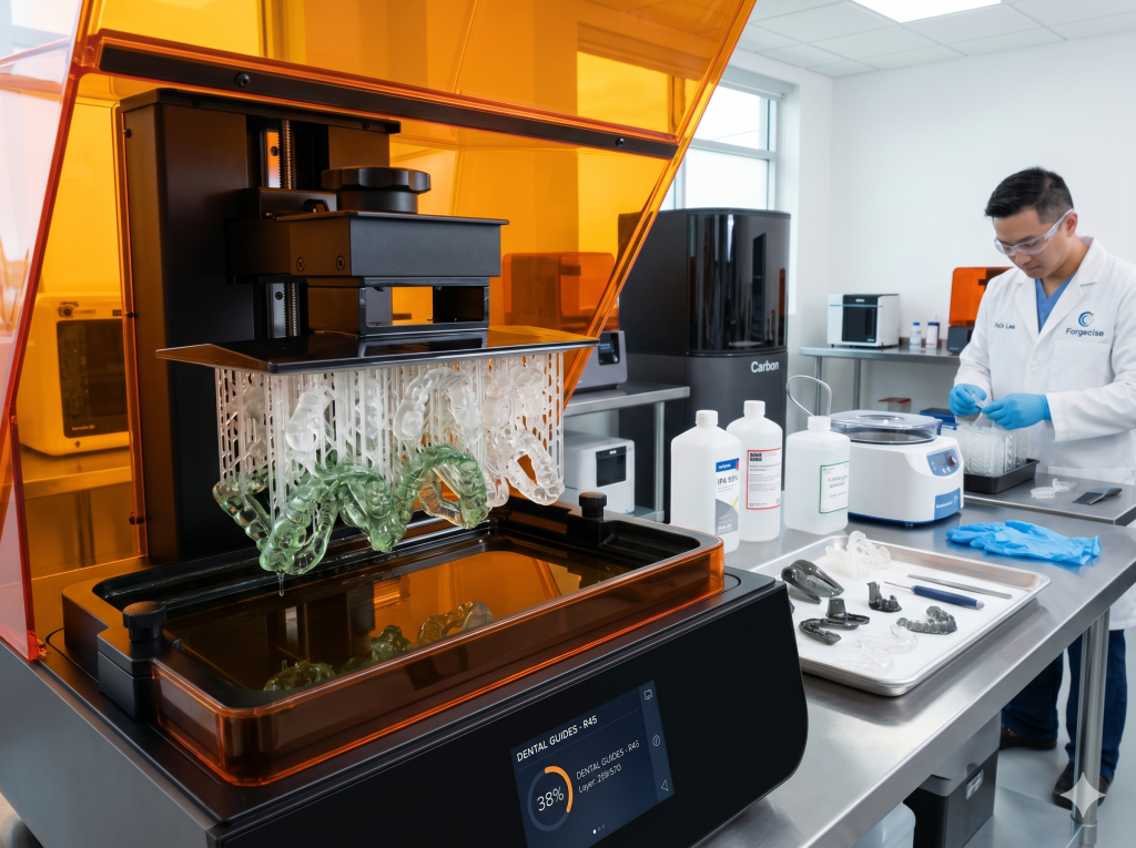
4.1 Dental Laboratories and Digital Integration
Dental laboratories were early adopters of digital workflows due to the critical need for highly customized, biocompatible, and patient-specific components.
[Intraoral Scan at Clinic] ---> [Direct Digital Transfer to Lab] ---> [Automated Nesting and High-Speed Print] ---> [Centrifugal Solvent-Free Post-Processing]
- Ziemek Laboratories: To address the rising costs and quality variations of outsourced dental models, Ziemek Laboratories integrated Carbon’s M Series Digital Light Synthesis (DLS) platforms under a subscription business model. By moving model and die production $100\%$ in-house, Ziemek achieved an immediate $12.5\%$ reduction in model fabrication costs, which grew to $27.5\%$ at full production efficiency. Furthermore, digital turnaround times were compressed by $40\%$, enabling same-day or next-day delivery to clinicians. The subscription model protected the lab against hardware obsolescence, as the printer hardware and software are continuously upgraded under the service agreement.
- Derby Dental Lab: To scale its high-volume thermoforming aligner business, Derby Dental transitioned production to Carbon’s L1 printer. While older stereolithography systems required $50\text{ minutes}$ to output eight solid arch models, the L1 platform produced $28$ solid models in under $40\text{ minutes}$. Additionally, implementing a solvent-free post-processing centrifuge system reduced washing and drying cycle times from $18\text{ minutes}$ to $7\text{ minutes}$, reclaiming $15$ labor hours per week and eliminating chemical solvent waste.
- NEO Lab: Transitioning to Carbon’s DLS allowed NEO Lab to print five full arches in $1.5\text{ hours}$, representing a $33\%$ throughput increase over polymer jetting systems. The lab experienced zero accuracy-related customer complaints across $1,300$ models produced in the first month, prompting immediate scaling with additional print engines.
- Corus Byrnes Dental Lab: After adopting the Carbon platform and integrated design software, Corus Byrnes reduced print failure rates from an industry-average $10\%$ to a microscopic $0.01\%$. This reliability enabled them to manufacture custom replacement dentures for dementia patients on demand in just $24\text{ hours}$, compared to the standard $10\text{-to-}12\text{-week}$ analog workflow.
4.2 Automotive Engineering and Rapid Tooling
In the automotive sector, vat polymerization serves as a critical bridge-to-production technology, bypassing the high costs and long lead times of metal injection tooling.
- Vital Auto: Industrial design studio Vital Auto uses vat polymerization to create high-fidelity prototypes and interior concept car components, bypassing the high costs and geographic bottlenecks of outsourced tooling. Utilizing robust resins such as Tough $2000$, engineers can print snap-fits, thin-walled enclosures, and threaded parts that mimic the structural integrity of molded ABS while preserving design geometry that is impossible to execute via traditional injection molding.
- Brose and Ford: By deploying high-throughput printers like Formlabs’ Form $4$ and Form $4\text{L}$, engineering teams have reduced component validation timelines. A large airflow test snout that required nearly $9\text{ hours}$ to print on older SLA platforms (Form $3+$) prints in under $3\text{ hours}$ on MSLA-based LFD systems, enabling multiple design-test-iterate cycles within a single working day.
4.3 Medical and Biocompatible Devices
The healthcare sector relies heavily on materials that can be sterilized, are biocompatible, and can be customized to match patient anatomy on demand.
- Preceptis Medical: To produce pediatric ear-tube delivery devices, Preceptis bypassed traditional aluminum tooling in favor of Carbon’s DLS process using MPU $100$ biocompatible resin. This allowed them to iterate designs rapidly, achieve surface finishes comparable to injection molding, and transition to on-demand, low-volume production with a fully traceable, digital workflow.
5. Professional and B2B Real-World Scaling Realities
While marketing materials often emphasize fast print speeds and high resolutions, experienced operators note that scaling vat polymerization requires managing a labor-intensive post-processing environment. On-site experience shared across professional networks reveals several operational factors that directly impact overall cost-per-part calculations.
[Design & Slice] ---> [Print Phase] ---> [Draining on Plate] ---> [Solvent Bath (IPA)] ---> [Support Removal] ---> [Thermal/UV Post-Cure]
5.1 Labor Intensity and Consumable Costs
Commercial print operations are highly labor-intensive, requiring continuous operator involvement for post-processing and machine maintenance.
- Post-Processing Workflow: Once a print is completed, the part exists in a “green state,” coated in unreacted liquid photopolymer. Operators must scrape parts from the metal build platform, wash them in isopropyl alcohol (IPA, $C_3H_8O$) or glycol ethers to dissolve surface monomers, and remove the sacrificial supports.
- Consumables and Safety: This workflow requires a continuous supply of nitrile gloves, respirators, protective eyewear, paper towels, and filter cones for resin recycling. The physical wear of manual scraping and cleaning can also lead to operator fatigue, skin irritation, and eventual allergic sensitization if safety protocols are not strictly enforced.
- Waste Management: The wash process generates resin-saturated solvent, which is classified as hazardous chemical waste. Before disposal in a sanitary landfill, this waste must be exposed to UV light to solidify the suspended photopolymer and filtered to comply with local environmental regulations, adding to the overall operational costs.
5.2 Commercial Print Farm Economics
At an industrial scale, additive manufacturing service bureaus leverage print farms to achieve economies of scale, purchasing resins in bulk $30\text{-liter}$ vats for large-format systems with build envelopes exceeding $25\times25\text{ cm}$. This scale reduces the per-part cost, making vat polymerization a viable alternative to low-volume injection molding.
However, operators emphasize that success requires highly consistent prints, as high failure rates can quickly erase profit margins. If a print fails, operators must pause production, drain and clean the resin vat, check the release film for debris, and reset the machine—resulting in lost machine uptime and wasted material.
6. Top 5 Technical Problems and Authoritative Engineering Solutions
An analysis of professional engineering forums (such as Reddit and Quora) highlights five recurring technical issues faced by operators. Below are the synthesized engineering solutions to these challenges.
H3: Q1: How to prevent cracking, splitting, and structural warping over time in hollowed resin prints?
Quick Answer: Design dual drainage holes of at least$2.0\text{ mm}$at opposite ends of the model to drain trapped liquid resin, wash the interior thoroughly with fresh IPA, and use internal UV micro-LEDs to cure the inner walls.
Unvented Cavity ---> Trapped Liquid Resin ---> Slow De-polymerization & Gas Build-up ---> Internal Pressure ---> Crack/Rupture
- The Cause: Operators frequently hollow out large, thick-walled parts in the slicer to conserve expensive resin and reduce peel-force failures during bottom-up printing. However, hollowing a model without creating sufficient venting paths creates a sealed interior chamber. During printing, liquid resin gets trapped inside this chamber. Because UV light cannot easily penetrate the outer walls during post-curing, this trapped liquid continues to off-gas and undergo slow de-polymerization. The trapped resin attacks the cured polymer walls from the inside, while the gas pressure builds until the model bursts or splits along its layer lines. Additionally, if the outer surface is heavily textured, it shrinks more during post-curing than the smooth interior wall, creating uneven surface tension and gradual warping.
- Authoritative Engineering Solution:
- Dual-Drain Hole Configuration: Every hollowed chamber must have at least two drainage holes positioned on opposite ends of the part to prevent suction-lock and facilitate complete resin drainage during washing.
- Minimum Hole Sizing: Drainage holes must have a minimum diameter of $2.0\text{ mm}$; smaller apertures trap viscous resin due to surface tension, rendering chemical flushes ineffective.
- Mechanical Interior Flushing: During post-processing, operators should inject clean IPA directly into the drain holes and shake the part vigorously, repeating the cycle until the effluent runs completely clear.
- Interior UV Curing: Insert miniature flexible UV-LED strips (e.g., fiber optic curing probes or specialized micro-LEDs) through the drainage holes to fully solidify the internal walls, neutralizing unreacted monomer and stabilizing internal stresses.
- Optimized Wall Thickness: Maintain a minimum wall thickness of $1.8\text{ mm to }3.0\text{ mm}$ for hollowed parts to withstand differential curing shrinkage.
H3: Q2: What is the most effective laboratory ventilation setup to control toxic VOC emissions and chemical odors?
Quick Answer: Place printers and wash stations inside negative pressure enclosures, and vent the exhaust directly outside using active inline duct fans positioned close to the exterior exit point.
Resin Vat/Wash Station ---> VOC/Monomer Release ---> Passive Carbon Masking (Ineffective) ---> Inhalation Risk
                                                ---> Negative Pressure Hood ---> Active Venting Out (Safe)
- The Cause: Liquid photopolymers release volatile organic compounds—such as acrylate monomers and photoinitiators—during both storage and UV exposure. While the VOC levels of PLA or PETG filaments are relatively low, liquid resins act as constant chemical sensitizers; repeated inhalation can lead to permanent respiratory allergies. Furthermore, standard desktop carbon filters or HEPA air purifiers are highly ineffective. Passive carbon filters only capture the largest, odor-causing molecules, masking the scent while allowing toxic, lighter VOCs to pass back into the room.
- Authoritative Engineering Solution:
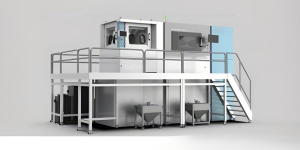
- Negative Pressure Enclosures: Printers and wash stations must be housed within sealed enclosures (such as industrial grow tents or laboratory fume hoods) maintained under continuous negative pressure.
- Active Inline Extraction: Enclosures must be vented directly to the exterior of the building using sealed ducting and high-airflow inline exhaust fans. The fan should be positioned close to the window/exhaust exit point rather than the enclosure, ensuring that any duct leaks pull fresh air in rather than pushing toxic air out into the room.
- Make-up Air Management: Active exhaust systems require a dedicated intake path to supply fresh “make-up” air, establishing a stable, one-way draft that prevents fumes from migrating back into living or office spaces.
- Consumable Waste Isolation: Spent paper towels, gloves, and failed prints must be immediately deposited into sealed hazardous waste bins and cured under UV light prior to final disposal.
H3: Q3: Why do prints fail to adhere to the build plate or stick permanently to the release film (FEP/nFEP/ACF)?
Quick Answer: Increase bottom layer exposure times to 10-15x normal, angle models at 30-45 degrees to reduce the cross-sectional print area, and ensure all protective plastic sheets are removed from new FEP films.
FEP Film Suction Force ---> Exceeds Support Tensile Strength ---> Part Separates and Adheres to Vat Floor
- The Cause: Bottom-up printing relies on a balance of adhesion: the cured resin layer must adhere strongly to the metal build plate (or the previous layer) and release easily from the FEP film. If the base exposure time is too low, the first layers fail to grip the build plate and remain stuck to the vat floor. Conversely, printing large, un-angled cross-sections creates significant suction force (suction-lock) during the peel step. This force can pull the cured layer off its supports, deform the part, or tear the FEP film. Additionally, operators often make the mistake of failing to peel the thin, protective plastic films from both sides of new replacement FEP liners before installation, resulting in compromised UV light transmission and immediate print failures.
- Authoritative Engineering Solution:
- Double Protective Film Removal: During FEP/nFEP replacement, carefully peel the protective sheets off both sides of the film. Verify the installation direction if specified by the manufacturer.
- Verify Tension and Height: Tension the film evenly across the vat frame using the manufacturer-specified spacer dimensions to ensure proper acoustic resonance and elastic recovery.
- Reduce Surface Cross-Sectional Area: Angle models in the slicer (typically at $30\text{ to }45\text{ degrees}$ along multiple axes) to minimize the surface area cured per layer, reducing peel forces.
- Optimize Exposure Profiles: Increase bottom layer exposure times (often $10\times\text{ to }15\times$ normal layer exposure, such as $30\text{ to }80\text{ seconds}$) to ensure the resin chemically bonds to the metal build plate. Lightly scuffing the metal build plate with 400-grit sandpaper can also help increase mechanical adhesion.
- Implement Rest Times (Light-Off Delay): Configure a $1\text{-second}$ rest time before curing and a $3\text{-second}$ rest time after retracting. This allows the liquid resin to fully settle and cool before exposure, ensuring stable layer formation.
- Avoid Mechanical Scrapers: Never touch the inside of the FEP film with a plastic or metal scraper. To remove cured failures, use the printer’s built-in “vat clean” function, which exposes the entire bottom layer of resin. You can then peel the cured sheet out as a single piece by lifting a sacrificial support corner.
H3: Q4: Why do temperature fluctuations in the workspace trigger print failures, and how do we manage resin viscosity?
Quick Answer: Warm the resin vat/bottles to at least$75^\circ\text{F}$($24^\circ\text{C}$) before printing, and use built-in vat heaters or chamber space heaters to keep the resin flowing smoothly.
Ambient Temp Drops (<65°F / 18°C) ---> Resin Viscosity Increases ---> Slow Flow Under Build Plate ---> Incomplete Curing & Delamination
- The Cause: Photopolymerization is an exothermic chemical reaction that is highly temperature-dependent. The chemical reactivity of standard and engineering resins is optimized to occur within a narrow thermal window of $70^\circ\text{F to }85^\circ\text{F}$ ($21^\circ\text{C to }29^\circ\text{C}$). When the temperature drops below $65^\circ\text{F}$ ($18^\circ\text{C}$), the viscosity of the liquid resin increases significantly. This highly viscous resin flows much slower, preventing it from leveling and filling the gap beneath the build platform before the next exposure cycle starts. This leads to incomplete curing, poor layer adhesion, and eventual structural delamination.
- Authoritative Engineering Solution:
- Integrated Vat/Chamber Heaters: For industrial operations, utilize printers with built-in, software-controlled vat heating elements. For desktop-class setups in cold climates, install miniature PTC heaters inside the printer enclosure.
- Pre-Heating Protocols: Prior to launching a print, ensure the resin bottle or vat is warmed to at least $75^\circ\text{F}$ ($24^\circ\text{C}$). Liquid resin should be thoroughly shaken and stirred to distribute heat and suspend settled pigments evenly.
- Thermal Isolation Enclosures: Place print stations inside insulated enclosures (such as thermal grow tents) equipped with small thermostatically controlled space heaters to maintain a stable microclimate throughout the entire print cycle.
H3: Q5: How do we calibrate exposure times and first-layer build plate leveling?
Quick Answer: Level the build plate using a standard A4 paper template under even downward pressure, and run interlocking calibration print arrays to find the exact exposure time for your specific resin.
Exposure Level:
[Under-Exposed]  ---> Thin features, poor layer adhesion, print separates.
[Optimal Curing] ---> Dimensions match CAD, crisp feature detail, reliable strength.
[Over-Exposed]   ---> Bloated features, tight tolerances bind, brittle parts.
- The Cause: Clear resins cure faster because light penetrates them more easily, whereas pigmented or highly filled engineering resins require more UV energy to initiate cross-linking. Over-exposure leads to blooming and oversized parts, while under-exposure results in thin, structurally weak features that fail to support their own weight. Furthermore, if the build plate is not parallel to the screen at the microscopic level, exposure will be uneven across the platform, leading to localized print failures.
- Authoritative Engineering Solution:
- Paper-Template Mechanical Leveling: Level the build plate using a thin, uniform piece of A4 paper rather than the thick cardboard templates provided by manufacturers. Tighten the leveling screws firmly while applying even downward pressure on the plate to ensure a minimal, parallel gap across the LCD screen.
- Run Standard Calibration Tests: Print a standardized exposure test array (such as the “Boxes of Calibration” or similar exposure matrices). These tests feature interlocking parts of specific thicknesses (e.g., $4\text{ mm}$, $6\text{ mm}$, and $8\text{ mm}$ boxes) that should slide together easily. If they are too loose, the print is under-exposed; if they bind or require force to assemble, the print is over-exposed.
- Optimize Slice and Speed Parameters: Avoid slicing at extreme resolutions (such as $0.03\text{ mm}$) unless printing high-detail models. A layer height of $0.05\text{ mm to }0.1\text{ mm}$ balances quality, speed, and success rates. For engineering resins, slow the lift speeds down to $30\text{ mm/min}$ to minimize mechanical stress on the newly cured layers.
7. Strategic B2B Procurement and Business Model Evaluation
For enterprise clients integrating vat polymerization into their production workflows, the procurement decision extends beyond simple printer costs and layer resolutions.
                         [B2B Procurement Evaluation]
                                      |
         -----------------------------------------------------------
        |                                                           |
[Direct CapEx Purchase]                                   [Subscription Service Plan]
  * Standard ownership.                                     * Zero obsolescence risk.
  * User-managed maintenance.                              * Turnkey hardware replacement.
  * Flexible third-party materials.                        * Predictable monthly costs.
  * Best for standard R&D.                                  * Best for nonstop production.
7.1 Hardware Acquisition Strategy
- Direct CapEx Purchase: Platforms like Formlabs offer low-cost entry points but carry self-maintenance risks. In continuous production environments, hardware downtime can lead to lost working days and delayed shipments. If pursuing CapEx ownership, operators must budget for spare parts, consumable release liners, and dedicated maintenance labor.
- Subscription Service Models: Subscription agreements, such as Carbon’s dental and industrial program, eliminate hardware obsolescence risks by automatically updating machines and software as technology improves. Additionally, full service plans often guarantee $24\text{-to-}48\text{-hour}$ hardware replacement, protecting the facility against unexpected production halts.
7.2 Production Quality and FMEA Integration
B2B operations must incorporate printer reliability into their Failure Mode and Effects Analysis (FMEA).
An independent third-party laboratory study evaluating printer reliability measured Formlabs’ Form $4$ as achieving a $98.7\%$ print success rate on its prints, compared to competing benchmark printers which failed $13.8\%$ to $25.3\%$ of the time.
In a high-throughput production environment, a $25\%$ failure rate means that one in four prints must be discarded, directly increasing part cost and labor overhead. Selecting platforms with high dimensional accuracy, automated diagnostics, and validated material settings is critical for maintaining consistent yield rates and high OEE.
8. Strategic Summary
For enterprise manufacturers looking to integrate vat polymerization, the path to profitability lies in balancing physical chemistry with operational rigor. By engineering the post-processing pipeline with automated centrifugal wash systems, containing volatile fumes through negative pressure extraction, and adopting reliable hardware ecosystems under optimized amortization models, organizations can fully realize the power of digital production.
To discuss how to integrate high-reliability MSLA/LFD or Carbon DLS systems into your specific manufacturing workflow, contact us at Forgecise today.