




Author: Felix Lee | CEO at Forgecise
Published: July 28, 2026
Topic: Laser Additive Manufacturing (LAM) Dedicated Alloy Design
Table of Contents
Quick Key Takeaway:
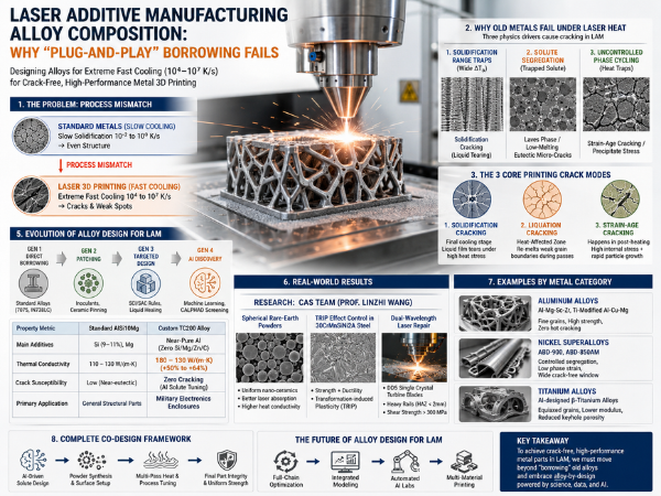
Standard metals (like 7075 aluminum or IN738 superalloys) were made for slow cooling ($10^{-2} \text{ to } 10^0 \text{ K/s}$). Laser 3D printing cools metal extremely fast ($10^4 \text{ to } 10^7 \text{ K/s}$). Mixing old metals with laser printing causes cracks, weak points, and uneven strength. To fix this, we must design new metals specifically made for laser printing processes.
1. The Problem with Using Old Metals in 3D Printing
Laser Additive Manufacturing (LAM)—including Laser Powder Bed Fusion (LPBF) and Directed Energy Deposition (DED)—lets us build complex metal parts layer by layer. A laser melts metal powder to create custom shapes that traditional factories cannot easily make.
However, many engineers make a basic mistake: they try to use standard commercial metals inside 3D printers.
Standard Metals (Slow Cooling)  ──>  Slow Solidification ($10^{-2} \text{ to } 10^0 \text{ K/s}$)  ──>  Even Structure
                                                               │
                                                    [ PROCESS MISMATCH ]
                                                               ▼
Laser 3D Printing (Fast Cooling) ──>  Extreme Fast Cooling ($10^4 \text{ to } 10^7 \text{ K/s}$)  ──>  Cracks & Weak Spots
Traditional metallurgy is like slow-cooking. Metals made for forging or casting cool down slowly. This slow pace lets elements mix evenly. On the other hand, a tiny laser pool in a 3D printer acts like flash-frying. It creates super-fast cooling rates ($10^4 \text{ to } 10^7 \text{ K/s}$) and sharp temperature changes ($10^4 \text{ to } 10^6 \text{ K/m}$).
If you use standard metals in a 3D printer, the part often warps, cracks, or breaks under stress. We must stop patching old metals and start making custom alloys designed for laser printing.
2. Why Old Metals Fail Under Laser Heat
Three main physical drivers cause standard metals to fail during laser printing:
                  ┌─────────────────────────────────────────┐
                  │    LAM Melt Pool Physics                │
                  │ Cool: 10⁴-10⁷ K/s | Grad: 10⁴-10⁶ K/m   │
                  └────────────────────┬────────────────────┘
                                       │
         ┌─────────────────────────────┼─────────────────────────────┐
         ▼                             ▼                             ▼
┌──────────────────┐          ┌──────────────────┐          ┌──────────────────┐
│ Solidification   │          │ Solute           │          │ Uncontrolled     │
│ Range Traps      │          │ Segregation      │          │ Phase Cycling    │
│ (Wide ΔT_s)      │          │ (Trapped Solute) │          │ (Heat Traps)     │
└────────┬─────────┘          └────────┬─────────┘          └────────┬─────────┘
         │                             │                             │
         ▼                             ▼                             ▼
Solidification Cracking       Laves Phase / Low-Melting      Strain-Age Cracking /
(Liquid Tearing)               Eutectic Micro-Cracks         Precipitate Stress
2.1 Problem #1: Wide Freezing Temperature Ranges
An alloy’s freezing range ($\Delta T_s = T_{\text{liquidus}} – T_{\text{solidus}}$) tells us how long it stays in a mixed liquid-solid state as it cools.
- AlCuMg Example: This aluminum alloy freezes over a wide gap ($534^\circ\text{C}$ to $642^\circ\text{C}$). In traditional casting, liquid metal fills in gaps as it cools slowly. In LPBF printing, long columnar grains grow quickly along the vertical build path. As the metal cools and shrinks, heat stress pulls on thin liquid pockets between the grains, ripping the metal open.
- Why 7xxx and 6xxx Aluminum Fail: Common high-strength alloys (like 7075, 7050, 6063, and 6061) crack during LPBF printing because their wide freezing windows leave liquid films open to stress for too long.
- Superalloy Cracks: High-strength nickel superalloys (like IN738LC) have high amounts of aluminum and titanium ($\text{Al} + \text{Ti} > 6 \text{ wt}\%$). This wide freezing gap causes low-melting liquid pockets that tear during quick cooling.
2.2 Problem #2: Chemical Segregation
Laser printing cools metal so fast that atoms get trapped before they can spread out evenly:
- Lattice Strain: Over-filled solid mixtures build up high internal strain, making the metal brittle.
- Low-Melting Weak Spots: Trapped elements collect at grain boundaries, forming low-melting mixtures that re-melt when the laser passes nearby again.
- Refractory Clustering in Nickel Metals: Heavy elements like Nb and Mo separate into spaces between grains. They form brittle Laves phases and hard carbides that block liquid metal flow and start small micro-cracks.
2.3 Problem #3: Unintended Heat Cycling
Every time the laser adds a new layer, it heats the layers underneath it again. The metal goes through quick heating and fast cooling over and over.
- Uneven Hardening: In alloys hardened by tiny particles (like nickel superalloys and Al-Zn-Mg-Cu alloys), repeated heat passes cause some areas to age too much while nearby areas remain under-aged.
- Strain-Age Cracking: Internal stress builds up over hundreds of heat passes. When the part is heat-treated later, hard $\gamma’$ particles form quickly under stress, tearing the grain boundaries.
- Low Toughness: High lattice strain and leftover heat stress lead to a common defect: low impact strength and poor fatigue life.
3. The 3 Types of Cracks in 3D Printed Metals
To make crack-free parts, we must know how different cracks form:
| Crack Type | Main Cause | How It Happens | Commonly Affected Metals |
|---|---|---|---|
| Solidification Cracking | Wide $\Delta T_s$ + High stress | Liquid films between grains tear during final cooling because liquid cannot flow in to fill the gap. | High-strength 7xxx/2xxx Al alloys, IN738LC, CM247LC |
| Liquation Cracking | Re-melting of weak boundaries | Next laser passes re-heat older layers; low-melting spots melt again; stress pulls them apart. | Cast Al alloys under high heat cycles, Ni superalloys |
| Strain-Age Cracking | Built-up stress + Rapid hard phases | Post-heat steps cause rapid $\gamma’$ phase growth while internal stress is still high, breaking the structure. | High $\text{Al}+\text{Ti}$ Nickel Superalloys ($\text{Al}+\text{Ti} > 6 \text{ wt}\%$) |
                       [ 3 Core Printing Crack Modes ]
                                   │
      ┌────────────────────────────┼────────────────────────────┐
      ▼                            ▼                            ▼
1. SOLIDIFICATION CRACKING   2. LIQUATION CRACKING        3. STRAIN-AGE CRACKING
   • Final cooling stage       • Heat-Affected Zone         • Happens in post-heating
   • Liquid film tears under     • Re-melts weak grain        • High internal stress +
     high heat stress            boundaries during passes       rapid particle growth
4. Why Welding Quality Does Not Equal Printability
Many engineers believe that a good welding metal is automatically good for 3D printing. This is wrong for three reasons:
- Pass Count and Size: Welding usually joins two pieces in one or two passes. 3D printing combines hundreds of thousands of microscopic weld passes over many hours.
- Stress Accumulation: Residual stress in welding stays local. In 3D printing, thermal stress stacks up across the entire height of the part.
- Quality Impact: A bad spot in a weld joint only affects a small seam. In 3D printing, the printed metal is the entire component. Small flaws weaken the whole product.
5. How Alloy Design Has Changed Over Time
Engineers have developed 3D printing metals through four stages:
Gen 1: Standard Metals (Old Forging/Casting Alloys: 7075, IN738)
  └──> Gen 2: "Patching" (Adding Powders & Ceramics: TiB₂, TiC, Zr/Si)
        └──> Gen 3: Targeted Alloys (SCI/SAC Math Rules, Liquid Healing)
              └──> Gen 4: AI & Data Discovery (Machine Learning + CALPHAD Software)
5.1 Second Generation: Patching Old Metals
Gen-2 fixes try to patch existing metals by adding small trace ingredients:
- Inoculants: Adding Ti and B to aluminum creates $Al_3Ti$ and $TiB_2$ particles. These particles help small round grains grow instead of long, weak columnar grains. In DED printing of Al7075, adding Zr/Si stops large cracks.
- Ceramic Particle Pinning: Adding tiny ceramic particles ($TiC$, $TiB_2$, $Y_2O_3$) blocks grain growth and keeps the structure fine.
- Drawbacks: Ceramic additions can clump together, react poorly, and make the metal brittle if too much is added.
5.2 Third Generation: Targeted 3D Printing Alloys
Gen-3 abandons old formulas and uses rapid cooling physics to build new alloys from scratch:
- Narrowing Freezing Ranges: Changing element ratios shrinks the $\Delta T_s$ gap. For example, adding silicon to Al-Cu-Mg creates an $Al\text{-}Si$ mixture ($577^\circ\text{C}$ melting point) that supplies extra liquid to fill gaps. This keeps AlSi10Mg from cracking.
- Cracking Formulas: Engineers use the Solidification Cracking Index (SCI) and Strain-Age Cracking (SAC) rules to calculate crack risks before making powders. Scientists used these rules to turn the crack-prone TMSL-1 superalloy into TMSL-2, reaching a tensile strength of 1195 MPa and 35.1% elongation without cracks.
- Self-Healing Liquids: Designing alloys to hold a tiny bit of liquid right as they freeze lets liquid fill in small shrinkage cracks automatically. In Al-Ce alloys, $\alpha\text{-Al} + \text{Al}_3\text{CeCu}$ mixtures suppress tearing.
- Non-Equilibrium Models: Modern math tools calculate how elements divide ($k_v$) under fast cooling speeds instead of relying on static phase charts.
| Generation | Main Approach | Key Methods | Common Examples |
|---|---|---|---|
| Gen 1 | Direct Borrowing | Uses standard equilibrium formulas | Standard 7075, IN738LC (high crack rates) |
| Gen 2 | Patching | Inoculants, ceramic pinning | Al7075 + Zr/Si, TiC-added Aluminum |
| Gen 3 | Targeted Design | SCI/SAC math rules, liquid healing | TMSL-2 Superalloy, Ti-modified AlCuMg |
| Gen 4 | AI Discovery | Machine learning, CALPHAD screening | TC200 High-Thermal Al, Keyhole-proof $\beta$-Titanium |
5.3 Fourth Generation: AI and Data-Driven Discovery
Gen-4 uses AI, machine learning, and thermodynamic software to scan millions of potential metal mixes:
- Multi-Property Balance: AI models look at dataset records across composition, process parameters, structure, and strength to optimize conductivities, ductility, and crack resistance at the same time.
- Fast Testing: Combining CALPHAD calculations with automated powder mixing cuts metal development time from years down to months.
6. Real-World Applications & Scientific Results
6.1 Industry Case Study: Sichuan Zenglong New Material Technology Co., Ltd.
Sichuan Zenglong New Material Technology Co., Ltd. was founded in September 2021 in the Chuan-Yu Gaozhu New Area. The company operates a 5,000-square-meter R&D facility with a 25-person research team holding 20 patents.
[ Sichuan Zenglong "366" Framework ]
  ├── 3 Metal Base Systems (Iron-based, Aluminum-based, Nickel/Titanium/Cobalt/Copper-based)
  ├── 6 Key Product Lines (Includes TC200, A100, 18Ni300, 4J32, 4J36)
  └── 6 Industry Focus Sectors (Military, Petrochemical, 3C, Aviation, Space, Auto/Motorcycle)
In July 2026, after expert reviews and factory evaluations, Sichuan Zenglong was named the Guang’an AI Computation New Material Additive Manufacturing Pilot Platform, serving as a regional center for 3D printing materials.
Breakthrough Case — TC200 High-Thermal Aluminum Alloy
Standard LPBF aluminum (AlSi10Mg) prints easily, but its thermal conductivity is low ($\sim 110\text{–}130 \text{ W/(m}\cdot\text{K)}$) and its tensile strength is moderate ($\text{UTS } 350\text{–}450 \text{ MPa}$). Printing pure aluminum for high thermal conductivity fails because it reflects laser light and cracks easily.
Using an AI platform combining high-throughput CALPHAD and multi-objective genetic algorithms, Sichuan Zenglong created TC200:
- Composition: Near-pure aluminum formulation containing no Si, Mg, Zn, or C elements.
- Performance: Gives a 50% to 64% boost in thermal conductivity over AlSi10Mg while printing completely crack-free.
- Usage: Successfully printed into large military heat enclosures and thermal controls that passed client testing.
| Property Metric | Standard AlSi10Mg | Custom TC200 Alloy |
|---|---|---|
| Main Additives | Si (9-11%), Mg | Near-Pure Al (Zero Si/Mg/Zn/C) |
| Thermal Conductivity | 110 – 130 W/(m·K) | 180 – 210 W/(m·K) (+50% to +64%) |
| Crack Susceptibility | Low (Near-eutectic) | Zero Cracking (AI Solute Tuning) |
| Primary Application | General Structural Parts | Military Electronics Enclosures |
Other Industrial Achievements:
- High-Strength Steels: Optimized process settings for A100 and 18Ni300 ultra-high-strength maraging steels, reaching high mechanical ratings.
- Low Thermal Expansion Alloys: Fixed thermal expansion shifts in Invar alloys (4J32 and 4J36) by linking metal ratios directly to expansion coefficients for stable output.
- “366” R&D Framework: Covers 3 main metal bases, 6 key product lines, and 6 core sectors (military, petrochemical, 3C electronics, aviation, aerospace, automotive/motorcycle), producing over 60 spherical powder formulas.
6.2 Research Case Study: CAS Team (Prof. Linzhi Wang)
Prof. Linzhi Wang’s team at the Chongqing Green and Intelligent Technology Institute, Chinese Academy of Sciences (CAS)—where Prof. Wang works as Deputy Director of the Chongqing 3D Printing Engineering Technology Center and a certified Senior AI Trainer—uses AI to design powders, tune processes, and repair parts.
                          [ CAS Prof. Linzhi Wang's Team ]
                                         │
     ┌───────────────────────────────────┼───────────────────────────────────┐
     ▼                                   ▼                                   ▼
Spherical Rare-Earth Powders        TRIP Effect Microstructure Control  Dual-Wavelength Laser Repair
• Uniform surface nano-ceramics     • 30CrMnSiNi2A Steel LPBF tuning    • DD5 Single Crystal LPBF
• Better laser energy absorption    • Combined strength and stretch      • Heavy Rails DED (HAZ < 2mm)
• Higher heat conductivity           boosts                             • Shear strength > 300 MPa
- Tailored Composite Powders: Created spherical rare-earth nano-composite powders with surface ceramic particles. This layout improves laser absorption and heat transfer in the melt pool.
- TRIP Effect Tuning: Decoupled process-microstructure links in LPBF printing of 30CrMnSiNi2A steel, using transformation-induced plasticity (TRIP) to boost strength and stretch capacity at the same time.
- Dual-Wavelength Laser Repairs:
- Turbine Blades: Used coaxial dual-wavelength laser powder bed repair on DD5 single-crystal turbine blades.
- Heavy Railway Tracks: Applied dual-wavelength DED repair to heavy train tracks, shrinking the Heat-Affected Zone (HAZ) to under 2 mm and lowering crack initiation risks by tenfold.
- High-Pressure Valves: Used laser cladding to rebuild seal faces on high-pressure manifold valve bodies, reaching bond shear strengths over 300 MPa.
- Standards & Awards: Led 1 powder testing standard, co-wrote 2 petrochemical 3D printing standards, and won an MIIT designation for turbine blade repair.
7. Examples by Metal Category
7.1 Aluminum Alloys
- Baseline: AlSi10Mg prints easily due to its near-eutectic silicon network, but tensile strength tops out around 350–450 MPa.
- High-Strength Custom Systems:
- Al-Mg-Sc-Zr Alloys: Form tiny $Al_3(Sc, Zr)$ particles during laser heat cycles, giving fine grains and tensile strengths above 550 MPa.
- Ti-Modified Al-Cu-Mg: Adds $Al_3Ti$ particles and adjusts element ratios to prevent hot tearing completely.
7.2 Nickel-Based Superalloys
- Baseline: Older superalloys (IN738LC, CM247LC) crack during printing due to high Al+Ti levels.
- Custom Solution: The Alloy-by-Design (ABD) method rebalances Al, Ti, Co, Ta, and W levels to make ABD-900 and ABD-850AM. These custom compositions limit element separation and lower phase strain during cooling, creating wide crack-free printing windows.
7.3 Titanium Alloys
- Baseline: Ti-6Al-4V is widely used, but its casting-based recipe forms coarse columnar grains and uneven structures.
- Custom Solution: ML-designed $\beta$-titanium alloys add solute elements that build rounded grain structures and match human bone stiffness better than commercial Ti-6Al-4V while reducing keyhole pore risks.
8. Summary & What Comes Next
       [ Complete Co-Design Framework ]
┌──────────────────────────────────────────────┐
│        AI-Driven Solute Design (Gen 4)        │
└──────────────────────┬───────────────────────┘
                       │
                       ▼
┌──────────────────────────────────────────────┐
│ Powder Synthesis & Surface Setup             │
└──────────────────────┬───────────────────────┘
                       │
                       ▼
┌──────────────────────────────────────────────┐
│ Multi-Pass Heat & Process Tuning             │
└──────────────────────┬───────────────────────┘
                       │
                       ▼
┌──────────────────────────────────────────────┐
│ Final Part Integrity & Uniform Strength      │
└──────────────────────────────────────────────┘
Main Points
- Standard Metals Do Not Work: Metals made for slow casting cannot handle $10^4\text{–}10^7 \text{ K/s}$ cooling rates without forming defects.
- Weldability Is Not Printability: Single-pass welding rules fail to predict multi-pass 3D printing results.
- The Design Shift: Alloy design is moving from Gen-1 “borrowing” and Gen-2 “patching” to Gen-3 “targeted recipes” and Gen-4 “AI discovery.”
- Crack Control Rules: Tools like SCI and SAC formulas help us build crack-free alloys.
- Real-World Results: Industrial teams like Sichuan Zenglong and researchers like Prof. Linzhi Wang’s team at CAS prove that combining AI, CALPHAD, and process tuning leads to better metal parts.
What Comes Next
- Full-Chain Optimization: Future alloy work will combine powder physics, laser pool behavior, heat cycling, and post-heat steps into one loop.
- Computer Simulations: Software will map the whole path: $\text{Process Settings} \rightarrow \text{Heat History} \rightarrow \text{Microstructure} \rightarrow \text{Part Strength}$.
- Automated AI Labs: Self-driving labs will make, print, test, and evaluate metal formulas automatically, cutting development times from years to days.
- Multi-Material Printing: Future designs will combine different metal compositions inside a single printed part.
9. Frequently Asked Questions (FAQ)
Q1: Why do standard high-strength aluminum alloys (like 7075) crack during LPBF 3D printing?
A: Standard 7075 aluminum has a wide freezing temperature gap designed for slow forging. During LPBF printing, fast cooling ($10^4\text{–}10^7 \text{ K/s}$) and sharp heat changes leave thin liquid films between growing grains. As the metal cools and shrinks, heat stress pulls these unbacked liquid films apart, causing hot cracks.
Q2: What is the main difference between weldability and printability?
A: Weldability measures how metal withstands a single heat pass in a small area. Printability measures how metal survives hundreds of thousands of overlapping heat passes where stresses build up across the full volume of the final part.
Q3: How does AI help design custom 3D printing alloys?
A: AI tools combine thermodynamic databases, fast-cooling math, and machine learning models trained on test data. They scan millions of metal mixtures to find compositions with narrow freezing gaps, good liquid flow, low element separation, and high strength without needing months of trial-and-error melting runs.
📚 References
- Song, B., Zhang, J., Zhang, Y., et al. Research progress in material design for metal laser additive manufacturing. Acta Metallurgica Sinica, 2023, 59(1): 1-15.
- Liu, Z., et al. Alloy design for laser powder bed fusion additive manufacturing: a critical review. International Journal of Extreme Manufacturing, 2024, 6(2): 29-63.
- Liu, T., Tan, C., et al. Alloy design paradigms in additive manufacturing: a new era of material innovation. International Journal of Extreme Manufacturing, 2026, 8(3).
- Development of a hot-cracking-free Ni-based superalloy for laser powder bed fusion via composition optimization. Journal of Materials Research and Technology, 2025.
- A quantitative model to determine the Ti content for crack-free AlCuMg alloy in laser powder-bed fusion. Journal of Manufacturing Processes, 2024.
- Progress in cracking mechanism and crack-resistant design of $\gamma’$-phase strengthened nickel-based superalloys by selective laser melting. Acta Metallurgica Sinica, 2023, 59(1).
- Sichuan Zenglong New Material Technology Co., Ltd. AI Calculation New Material Additive Manufacturing Pilot Platform Technical Report, 2026.
- Sichuan Zenglong New Material Technology Co., Ltd. High Thermal Conductivity Aluminum Alloy TC200 Material Specification, 2025.
- Chongqing Institute of Green and Intelligent Technology, Chinese Academy of Sciences (Prof. Linzhi Wang’s Team). Coaxial dual-wavelength laser powder bed repair of single-crystal superalloy turbine blades. Journal of Alloys and Compounds, 2025.
- Chongqing Institute of Green and Intelligent Technology, Chinese Academy of Sciences (Prof. Linzhi Wang’s Team). LPBF process parameter control of TRIP effect in 30CrMnSiNi2A steel. Journal of Iron and Steel Research International, 2026.