






By Felix Lee, CEO at Forgecise | Published: July 24, 2026
Table of Contents
Quick Summary & Core Takeaways
- Definition: Metal Additive Manufacturing (MAM) builds 3D metal parts layer-by-layer directly from digital CAD files using focused heat (lasers, electron beams, electric arcs) or kinetic friction.
- Primary Fusion Technologies:
- Laser Powder Bed Fusion (LPBF / SLM): Best dimensional accuracy ($\pm0.05\,\text{mm}$) and surface finish. Works well for fine internal channels and lattices.
- Electron Beam Melting (EBM): Runs under vacuum ($10^{-4}\,\text{mbar}$) with warm powder bed preheating ($600^\circ\text{C} – 1000^\circ\text{C}$). Reduces thermal stress and stops cracking in reactive metals ($\text{Ti6Al4V}$,$\text{CoCr}$).
- Directed Energy Deposition (DED / LMD / WAAM): Fast build rates ($>1\,\text{kg/h}$). Built for large structural builds, repairs, and cladding.
- Solid-State Methods: Friction Stir AM (FSAM) and Ultrasonic AM (UAM) bond metals below melting points, skipping shrinkage, porosity, and thermal cracking.
- The Complete Production Chain: Success requires good feedstock quality (Gas Atomization, PREP), digital geometry optimization, controlled cooling ($10^3 – 10^6\,^\circ\text{C/s}$), and post-processing like Hot Isostatic Pressing (HIP) and solution heat treatments to dissolve brittle phases (such as Laves phase in superalloys) and seal pores.
1. Introduction to Metal Additive Manufacturing (MAM)
1.1 What is Metal Additive Manufacturing?
Metal Additive Manufacturing (MAM)—often called industrial metal 3D printing—changes how we make high-performance metal parts. Traditional subtractive manufacturing (like CNC milling or turning) shapes parts by cutting material away. Formative manufacturing (like forging or casting) uses molds and pressure. In contrast, MAM forms metal structures using a “discrete-stacking” (layer-by-layer) method.
Subtractive: [Solid Block]  ──(Material Removal)──> [Final Part] + [Massive Scrap]
Formative:   [Liquid Metal] ──(Molding / Forging)─> [Final Part] (High Tooling Cost)
Additive:    [CAD Model]    ──(Layer Stacking)───> [Final Part] (Near-Zero Waste)
By slicing 3D computer-aided design (CAD) models into thin 2D layers, MAM machines selectively melt, fuse, or bond metal powder or wire to create near-net-shape components. This process offers wide design freedom, cuts material waste, and removes the need for custom tooling.
1.2 Historical Lineage
The technical roots of MAM span four decades of work across materials science, lasers, optics, and industrial controls:
- 1980s (Early Polymer Steps): Early 3D printing used light-cured polymers via stereolithography (SLA). Metallurgists began testing mixtures of polymer binders and metal powders, borrowing concepts from powder metallurgy.
- 1990s (The Fusion Shift): Commercial metal printing arrived. EOS GmbH (Germany) commercialized Laser Powder Bed Fusion (under the name Selective Laser Melting, SLM). Around the same time, Arcam AB (Sweden) developed commercial Electron Beam Melting (EBM) systems.
- 2000s–Present (Industrial Production): MAM shifted from basic prototypes to production of critical, load-bearing parts in aerospace, defense, medical implants, and automotive systems.
1980s: Polymer SLA & early powder metallurgy experiments
  │
1990s: Launch of EOS Selective Laser Melting (SLM) & Arcam Electron Beam Melting (EBM)
  │
2000s: Multi-laser production machines and high-rate DED platforms
  │
2020s+: Real-time optical monitoring, AI-assisted design, and flight-ready parts
1.3 ASTM AM Classification Framework & Material Matrix
The American Society for Testing and Materials (ASTM International) under the ASTM F2792 / ISO 52900 standard splits additive manufacturing into seven core process types:
- Powder Bed Fusion (PBF)
- Directed Energy Deposition (DED)
- Binder Jetting (BJ)
- Material Extrusion (ME)
- Sheet Lamination (SL)
- Material Jetting (MJ)
- Vat Photopolymerization (VP)
Feedstock and Process Compatibility
- Sheet Lamination (SL): Uses metal foils or thin sheet metal.
- Material Extrusion (ME): Uses polymer-bound metal filaments or wire.
- Vat Photopolymerization (VP): Uses liquid photo-curable resins (mostly for polymers and ceramic slurries).
                      ┌─────────────────────────────────────────┐
                      │    ASTM 7 AM Process Classification     │
                      └────────────────────┬────────────────────┘
                                           │
         ┌─────────────────────────────────┼─────────────────────────────────┐
         │                                 │                                 │
  [Polymers / Resins]               [Metals & Ceramics]               [Sheet / Foil]
  ├── Vat Photopolymerization (VP)  ├── Powder Bed Fusion (PBF)       └── Sheet Lamination (SL)
  ├── Material Jetting (MJ)         ├── Directed Energy Deposition(DED)
  ├── Binder Jetting (BJ)           └── Binder Jetting (BJ)
  └── Material Extrusion (ME)
| Material Group | Applicable ASTM Processes | Core Characteristics in Metal Processing |
|---|---|---|
| Polymers | VP, BJ, MJ, ME, PBF | Highest process compatibility; wide processing windows. |
| Metals | PBF, DED, BJ, ME, SL | Needs high heat (lasers, electron beams, arcs) or kinetic force to achieve full consolidation and high density. |
| Ceramics | PBF, BJ, ME, VP | High melting points; vulnerable to thermal stress cracking; often uses binder jetting followed by furnace sintering. |
2. Classification of Metal AM Technologies
Metal Additive Manufacturing systems fall into two basic groups depending on whether the metal fully melts and re-solidifies (Fusion-Based Metal AM) or joins without melting via atomic diffusion (Solid-State Metal AM).
                         ┌───────────────────────────────────┐
                         │   Metal Additive Manufacturing    │
                         └─────────────────┬─────────────────┘
                                           │
                  ┌────────────────────────┴────────────────────────┐
                  │                                                 │
       [Solid-State Metal AM]                            [Fusion-Based Metal AM]
       (No Liquefaction / No Melting)                    (Liquid-Phase Melting & Solidification)
       ├── Friction Stir AM (FSAM)                       ├── Powder Bed Fusion (PBF)
       └── Ultrasonic AM (UAM)                           │   ├── Laser Powder Bed Fusion (LPBF / SLM)
                                                         │   └── Electron Beam Melting (EBM)
                                                         └── Directed Energy Deposition (DED)
                                                             ├── Laser Metal Deposition (LMD / LENS)
                                                             └── Wire Arc AM (WAAM)
2.1 Solid-State Metal AM
Solid-state systems join metals well below their melting temperatures ($T_m$). This avoids melting defects like solidification cracking, gas keyholes, alloy segregation, and heavy thermal strain.
1. Friction Stir Additive Manufacturing (FSAM)
- Process: Based on friction stir welding (FSW). A hard rotating tool pin presses into stacked solid metal sheets. Frictional heat and heavy plastic deformation force the metal into a superplastic state, joining layers without liquid melting.
- Strengths: Low heat input, high joint density, fine equiaxed grain structures, low distortion, and small residual stresses.
- Common Uses: Thick aluminum, magnesium, and copper plates or structural blocks.
2. Ultrasonic Additive Manufacturing (UAM)
- Process: Combines high-frequency ultrasonic waves ($20\,\text{kHz}$) with continuous pressure rolls. Thin metal foils stack sequentially; an ultrasonic horn (sonotrode) applies downward force and side-to-side motion. This breaks up surface oxides and drives solid-state atomic diffusion across the metal contact points.
- Strengths: Operates at low temperatures (often $<30\%\,T_m$). This lets engineers embed sensors, optical fibers, or build multi-metal layers (e.g., Al-to-Cu, Ti-to-Steel) without making brittle intermetallic compounds.
2.2 Fusion-Based Metal AM
Fusion systems use concentrated heat sources to melt metal powder or wire into a small melt pool, which solidifies as it moves. The two main groups are Powder Bed Fusion (PBF) and Directed Energy Deposition (DED).
3. Core Technologies: LPBF, EBM, and DED
  Laser Powder Bed Fusion (LPBF)        Electron Beam Melting (EBM)          Directed Energy Deposition (DED)
 ┌──────────────────────────────┐     ┌──────────────────────────────┐     ┌──────────────────────────────┐
 │ • Fiber Laser Source         │     │ • High-Energy Electron Gun   │     │ • Diode/CO2 Laser or Arc     │
 │ • Argon Inert Gas Shield     │     │ • High Vacuum Chamber        │     │ • Coaxial Powder/Wire Nozzle │
 │ • Low Preheat Temperatures   │     │ • High Preheat (600-1000°C)  │     │ • Local Gas Shielding        │
 │ • Fine Fine Details & Finish │     │ • Low Stress / Fast Scan     │     │ • High Deposition Rates      │
 └──────────────────────────────┘     └──────────────────────────────┘     └──────────────────────────────┘
3.1 Laser Powder Bed Fusion (LPBF / SLM)
Process Mechanism
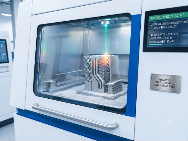
LPBF (also called Selective Laser Melting, SLM; Direct Metal Laser Sintering, DMLS; or Selective Laser Sintering, SLS / Selective Heat Sintering, SHS) uses a fiber laser ($200\,\text{W} – 1000\,\text{W}$) aimed by fast galvanometer mirrors. A precision blade spreads a thin layer of metal powder ($15 – 53\,\mu\text{m}$) over a build plate inside a sealed build chamber. Inert gas (Argon or Nitrogen) keeps oxygen levels under $100\,\text{ppm}$. The laser scans the layer path, fully melting the metal powder into a solid layer.
       [Galvanometer Scanner] ───┐
                                 │ Laser Beam
                                 ▼
   [Powder Reservoir] ──> [Recoater Blade] ──> [Powder Bed] ──> [Laser Melt Pool]
                                                                     │
                                                               [Substrate Plate]
                                                                     │
                                                              [Elevator Down]
Strengths
- High Precision: Maintains tolerances down to $\pm0.05\,\text{mm}$ and clean surface finishes ($Ra \approx 6.3 – 15\,\mu\text{m}$).
- Complex Shapes: Builds thin walls, internal cooling channels, and complex lattice grids (like Gyroid or Schwarz Primitive forms).
- Broad Alloy Selection: Compatible with proven production alloys ($\text{316L}$, $\text{17-4PH}$, $\text{Ti6Al4V}$, $\text{Inconel 718}$, $\text{CoCr}$, $\text{AlSi10Mg}$).
Limits
- Thermal Stress: Sharp temperature changes ($\Delta T$) cause high internal tension, requiring support anchors and post-print heat stress relief.
- Post-Processing Work: Removing supports requires wire EDM cutting, grinding, or CNC milling.
- Build Speed: Slower build volume rates compared to DED methods.
Typical Uses
- Aerospace turbine blades, liquid rocket engine injectors, injection mold cooling inserts, dental implants, and custom joint replacements.
3.2 Electron Beam Melting (EBM)
Process Mechanism
Commercialized first by Arcam (now GE Additive), EBM uses a high-voltage electron gun ($60\,\text{kV}$) to accelerate electrons to $0.1-0.4\times$ the speed of light. Magnetic coils focus and steer the electron beam over a bed of coarse metal powder ($45 – 105\,\mu\text{m}$). The entire build runs inside a high-vacuum chamber ($10^{-4} – 10^{-5}\,\text{mbar}$).
          [Electron Gun / Cathode]
                     │ High Voltage Beam
                     ▼
         [Electromagnetic Lenses] (Focus & Deflect)
                     │
                     ▼
   [Vacuum Chamber: 10^-4 mbar] ──> [Preheated Powder Bed: 600–1000°C]
Before melting each layer, the electron beam scans the powder bed at high speeds ($>10,000\,\text{mm/s}$) to preheat the powder bed to $600^\circ\text{C} – 1000^\circ\text{C}$. This light sintering steps keeps the bed warm, reducing thermal shocks during the primary melting pass.
Strengths
- Low Thermal Tension: Bed preheating flattens thermal gradients, keeping internal stress low and enabling support-free builds on complex parts.
- Vacuum Atmosphere: Stops oxygen pickup in reactive metals ($\text{Ti6Al4V}$, Titanium Aluminide $\text{TiAl}$).
- Fast Scan Speeds: Magnetic coil deflectors move the beam almost instantly across multiple points.
Limits
- Coarser Surface: Larger powder particles yield rougher surfaces ($Ra \approx 20 – 50\,\mu\text{m}$), requiring CNC machining on functional contact surfaces.
- High Operating Cost: High vacuum pumps and electron beam optics increase equipment expenses.
- Fewer Alloys: Works mainly on conductive alloys with verified sintering traits ($\text{Ti6Al4V}$, $\text{Ti-48Al-2Cr-2Nb}$, $\text{CoCrMo}$).
Typical Uses
- Structural jet engine turbine blades (TiAl), aerospace brackets, and orthopedic hip cups.
3.3 Directed Energy Deposition (DED / LMD)
Process Mechanism
DED systems (also known as Laser Metal Deposition, LMD; Laser Engineered Net Shaping, LENS; Direct Light Fabrication, DLF; or Wire Arc Additive Manufacturing, WAAM) feed powder or wire directly into a melt pool created by a laser, electron beam, or electric arc. Mounted on multi-axis CNC gantries or robotic arms, the nozzle deposits metal directly onto existing parts or base plates.
       [Laser / Arc Power Source]
                  │
                  ▼
   [Coaxial Powder Feed / Wire Feed] ──> [Focused Thermal Melt Pool]
                                                 │
                                     [Substrate Component / Part]
                                                 │
                                   [Multi-Axis Robotic Motion]
Strengths
- High Build Rates: Material throughput ranges from $0.5\,\text{kg/h}$ (laser powder systems) up to $>5\,\text{kg/h}$ (wire arc WAAM).
- Large Build Volumes & Repair: Unconstrained build envelopes allow repairs on large turbine shafts, worn flanges, or adding ribs to forged parts.
- Multi-Material Mixes: Dual powder hoppers can blend composition ratios on the fly to build Functionally Graded Materials (FGMs).
Limits
- Coarser Resolution: Low accuracy and rough surfaces require secondary CNC finishing.
- Coarser Grain Structures: High heat input creates larger melt pools and slower cooling, leading to larger directional grains.
- Overhang Restrictions: Cannot print fine unsupported horizontal overhangs or small lattices without continuous multi-axis rotation.
Typical Uses
- Repairing turbine blisks, hardfacing oil drill bits, large structural crossbeams (WAAM), and rocket nozzle skirts.
3.4 Technology Comparison Matrix
| Operating Parameter | Laser Powder Bed Fusion (LPBF) | Electron Beam Melting (EBM) | Directed Energy Deposition (DED) |
|---|---|---|---|
| Heat Source | Fiber Laser ($200 – 1000\,\text{W}$) | Electron Beam ($60\,\text{kV}$) | Fiber/Diode Laser, Arc, Plasma |
| Feedstock | Fine Powder ($15 – 53\,\mu\text{m}$) | Coarse Powder ($45 – 105\,\mu\text{m}$) | Coarse Powder ($45 – 150\,\mu\text{m}$) / Wire |
| Build Atmosphere | Inert Gas (Argon / Nitrogen) | High Vacuum ($10^{-4}\,\text{mbar}$) | Inert Shielding Gas Jet / Sealed Box |
| Bed Preheat Temp | Ambient to $200^\circ\text{C}$ (up to $500^\circ\text{C}$) | $600^\circ\text{C} – 1000^\circ\text{C}$ | Unheated / Localized Induction |
| Dimensional Precision | High ($\pm0.05\,\text{mm}$) | Moderate ($\pm0.2\,\text{mm}$) | Low ($\pm0.5 – 1.0\,\text{mm}$) |
| Surface Finish ($Ra$) | $6.3 – 15\,\mu\text{m}$ | $20 – 50\,\mu\text{m}$ | $>40\,\mu\text{m}$ |
| Deposition Speed | Low ($10 – 100\,\text{cm}^3\text{/h}$) | Medium ($100 – 500\,\text{cm}^3\text{/h}$) | High ($500 – 5000+\,\text{cm}^3\text{/h}$) |
| Residual Stress | Very High (Needs supports & stress relief) | Low (Relieved during preheated build) | Moderate to High |
| Primary Focus | Fine features, thin walls, internal channels | Medium-to-large reactive alloy structural parts | Large-scale fabrication, repair & cladding |
4. The End-to-End MAM Technical Chain
Transforming raw metal into a finished, flight-certified component requires careful management across three steps: Pre-Processing, In-Process Production, and Post-Processing.
┌──────────────────────────────────────────────────────────────────────────────────────────┐
│                             END-TO-END MAM PROCESS CHAIN                                 │
└──────────────────────────────────────────────────────────────────────────────────────────┘
  [1. PRE-PROCESSING]
   ├── Feedstock Prep: Gas Atomization (GA), PREP, Wire Drawing, Water Spinning
   └── Digital Design: CAD -> Topology Optimization -> Lattice Tuning -> Slicing (STL)
          │
          ▼
  [2. IN-PROCESS MANUFACTURING]
   ├── Energy-Powder Physics (Melt Pool Dynamics, Cooling Rates 10^3–10^6 °C/s)
   └── Parameter Tuning: Laser Power, Scan Speed, Hatch Spacing, Layer Thickness, Gas Atmosphere
          │
          ▼
  [3. POST-PROCESSING]
   ├── Support Removal & CNC Finish Machining
   ├── Stress Relief & Solution Heat Treatment (e.g., Laves Phase Dissolution)
   └── Hot Isostatic Pressing (HIP): Closing Internal Gas Porosity & Micro-Cracks
4.1 Pre-Processing Phase
Feedstock Production & Powder Quality
Powder traits determine build stability and defect rates. Key metrics include Particle Size Distribution (PSD), Sphericity, Satellite Particle Density, Oxygen/Nitrogen Content, Internal Porosity (Hollow Spheres), and Hall Flowability.
 Powder Atomization Methods:
 1. Gas Atomization (GA):         Liquid Stream ──(Supersonic Gas Jets)──────> Spherical Powder
 2. Plasma Rotating Electrode:   Rotating Rod  ──(Plasma Torch + Centrifugal Force)──> Ultra-Pure Powder
 3. Ultrasonic Atomization:     Liquid Stream ──(Ultrasonic Vibrating Horn)───> Fine Droplets
- Gas Atomization (GA):
- Process: Liquid metal exits a ceramic nozzle and meets high-speed inert gas jets (Argon/Nitrogen). The kinetic energy shatters the stream into fine droplets, which round out and freeze into spherical powder.
- Traits: Yields large quantities, but trapped gas can create tiny hollow spheres (“hollow powder”), leading to gas porosity in printed parts.
- Plasma Rotating Electrode Process (PREP):
- Process: A fast-spinning alloy rod ($>15,000\,\text{RPM}$) has its tip melted by a plasma torch. Centrifugal force flings liquid droplets off the edge into a collection tank filled with inert gas.
- Breakup Dynamics: Droplets form via direct separation, liquid line breakup, and liquid film breakup modes. Liquid film breakup produces wider size distributions with occasional irregular shapes.
- Traits: Yields highly spherical powder free of satellite particles and hollow voids. Best for high-purity $\text{Ti6Al4V}$ and superalloys.
- Ultrasonic Atomization:
- Process: Uses high-frequency sound waves from a contact horn or transducer to shatter molten metal into uniform droplets.
Wire Feedstock Manufacturing
For wire-fed DED platforms, quality depends on composition purity, surface cleanliness, diameter tolerances, wire feeding friction, and wire cast. Production paths include:
- Wire Drawing: The main industrial path for ductile alloys, shape memory metals (SMA), and High Entropy Alloys (HEAs).
- Rotary Water Spinning: Created by Ohnaka et al., this quenches liquid metal jets inside a spinning water ring to produce amorphous and shape-memory wire.
- Glass Coating Method: Used for fine micro/nano-wires (e.g., Fe-based, Ni-based amorphous alloys, $\text{Cu-Sn}$, and $\text{Ni}_2\text{MnGa}$ micro-wires).
- Melt Extraction: Introduced by Maringer and Mobley (1972), a fast-spinning chilled wheel touches a molten metal bath, pulling fine wire filaments out ($\text{Zr}$-based and $\text{Ti}$-based amorphous alloys).
Digital Workflow & Geometric Optimization
The digital steps optimize geometry specifically for additive production rather than subtractive machining:
[CAD 3D Solid Model] ──> [Topology Optimization] ──> [Lattice Structure Integration]
                                                             │
[Machine Toolpath Code] <── [2D Layer Slicing] <─── [STL / AMF File Conversion]
- Topology Optimization (TO): Algorithms rearrange material based on load patterns, placing strength where stresses concentrate and removing unneeded metal to maximize stiffness-to-weight ratios ($E/\rho$).
- Lattice Integration: Fits Triply Periodic Minimal Surface (TPMS) or unit-cell lattices (like IsoTruss or octet-truss) into open spaces to build porous medical structures or lightweight heat exchangers.
- Generative Design: Uses multi-physics simulations to iterate geometries for weight, strength, thermal control, and print orientation simultaneously.
4.2 In-Process Thermal Physics
During fusion printing, laser energy hits powder over microsecond time frames. Rapid cooling rates ($10^3 – 10^6\,^\circ\text{C/s}$) and sharp thermal gradients ($\nabla T$) drive non-equilibrium phase transformations.
                  ┌─────────────────────────────────────────┐
                  │ Focused Laser Beam / Energy Input       │
                  └────────────────────┬────────────────────┘
                                       │
                                       ▼
                  ┌─────────────────────────────────────────┐
                  │ Keyhole / Conduction Melt Pool Dynamics │
                  │  • Thermal Gradient (∇T)                │
                  │  • Rapid Cooling: 10^3 – 10^6 °C/s      │
                  └────────────────────┬────────────────────┘
                                       │
       ┌───────────────────────────────┴───────────────────────────────┐
       │                                                               │
       ▼                                                               ▼
┌───────────────────────────────────────────┐     ┌───────────────────────────────────────────┐
│ Primary Process Parameters                │     │ Physical Phenomena Driven                 │
│ • Laser Power (P), Scan Speed (v)         │     │ • High Nucleation Rate / Fine Grains      │
│ • Hatch Spacing (h), Layer Thickness (t)  │     │ • Non-Equilibrium Metastable Phases      │
│ • Volumetric Energy Density (VED = P/vht) │     │ • Residual Stress & Marangoni Convection  │
└───────────────────────────────────────────┘     └───────────────────────────────────────────┘
Observations from Empirical Research
- Laser Preheat Tuning (Bagehorn et al.): Base plate preheating reduces thermal strain, cuts laser power demands, improves powder wetting, and prevents part cracking without losing dimensional tolerance.
- Inert Gas Atmosphere & Cooling (Khorasani et al.): Pure inert gas prevents metal oxidation. Extreme cooling speeds ($10^3 – 10^6\,^\circ\text{C/s}$) boost thermal nucleation rates and limit grain growth, creating refined microstructures.
- Melt Pool Dynamics (Bruschi et al.): Melt pool shape, temperature gradients, and solidification behavior depend on parameter interactions:
$$\text{VED} = \frac{P}{v \cdot h \cdot t}$$
(Where $P$ = Laser Power, $v$ = Scan Speed, $h$ = Hatch Spacing, $t$ = Layer Thickness).
- EBM Powder Bed Preheat (Wang Yajuan et al.): Preheating powder beds to $600^\circ\text{C} – 1000^\circ\text{C}$ stabilizes temperatures, lowers heat gradients, and improves layer-to-layer bonding.
- EBM Chamber Vacuum (Cui Yadi et al.): High vacuum environments ($10^{-4}\,\text{mbar}$) prevent oxygen absorption in titanium alloys.
- Beam Scan Movement (Li Longfei et al.): Fast beam movement shortens laser contact time, keeping energy inputs consistent while limiting total internal thermal stress build-up.
- EBM Parameter Interdependence (Yu et al.): Beam current, focus offset, speed, and bed preheat settings interact to alter grain growth boundaries.
- DED Powder Feeding (Qin Renyao et al.): Synchronous powder delivery builds dense melt pools with minimal bulk porosity and strong mechanical properties.
- Open-Air DED Shielding (Wu Yuqin et al.): Localized inert gas shielding protects weld pools from oxidation in open robotic cells.
- DED Heat Patterns (Huang Weibo et al.): Higher total power inputs produce sharper thermal gradients, forming larger directional dendritic grains compared to LPBF.
4.3 Post-Processing Phase (Unlocking Material Performance)
As-printed parts retain internal stress, non-equilibrium microstructures, anisotropic grains, and occasional micro-voids. Targeted post-processing fixes these issues to meet end-use specifications.
As-Printed Part ──> [1. Support Removal] ──> [2. Stress Relief Heat Treat] ──> [3. Hot Isostatic Pressing] ──> [4. Finish Machining]
 (High Residual      (EDM / CNC Cut)          (Dissolve Brittle Phases,          (Apply 100-200 MPa Argon Pressure   (Precision Surface
  Stress & Porosity)                           e.g., Laves Phase)                  at Elevated Temperatures)            Grinding / Polishing)
Support Removal & Surface Machining
Parts are cut from build plates using Wire Electrical Discharge Machining (Wire EDM) or band saws. Supports are cleared by hand tools or CNC mills, followed by final machining on critical mating faces and threaded holes.
Thermal Processing & Microstructure Alignment
Controlled heat cycles relieve internal tension, promote recrystallization, and dissolve brittle non-equilibrium phases.
- Dissolution of Laves Phase in Superalloys (Luo et al.): In as-printed LPBF Inconel 718 ($\text{IN718}$), Niobium segregation creates a brittle intermetallic Laves phase $(\text{Ni, Co, Fe})_2(\text{Nb, Ti, Si})$ along grain boundaries. This phase lowers tensile ductility and fatigue life.
- Solution heat treatment between $980^\circ\text{C}$ and $1230^\circ\text{C}$ modifies this structure:
- At $980^\circ\text{C} – 1000^\circ\text{C}$, continuous Laves networks break apart into small individual particles.
- At $1080^\circ\text{C}$, the Laves phase converts into round globular shapes.
- Above $1180^\circ\text{C} – 1230^\circ\text{C}$, the Laves phase dissolves completely into the $\gamma$-matrix. This homogenizes the structure and releases Niobium for strengthening precipitation ($\gamma”-\text{Ni}_3\text{Nb}$).
Hot Isostatic Pressing (HIP)
Hot Isostatic Pressing subjects parts to simultaneous elevated temperatures ($1000^\circ\text{C} – 1200^\circ\text{C}$) and high gas pressure ($100 – 200\,\text{MPa}$ Argon) inside a pressure vessel.
       Ar Argon Pressure (100–200 MPa) ──┐
                                          │
   Elevated Temp (1000–1200°C) ───────> [HIP Chamber] ──> [Plastic Flow & Plastic Yielding]
                                                                   │
   Internal Void Collapse <────────────────────────────────────────┘
- Void Closure Physics: High heat and equal surrounding gas pressure trigger local plastic flow, creep, and atomic diffusion across internal void walls. This collapses keyholes, gas pores, and lack-of-fusion voids without altering external part dimensions.
- Microstructure Changes in LPBF IN738-0.3C Superalloy:
- High-resolution X-ray computed tomography shows HIP treatment reduces total pore volume to near zero ($>99.9\%$ theoretical density).
- As-printed melt pool boundaries dissolve, and fine dendritic structures recrystallize into uniform, equiaxed grains, improving high-temperature creep life.
5. Industrial Applications & Real-World Use Cases
                               ┌─────────────────────────────────────────┐
                               │       MAM Industrial Applications       │
                               └────────────────────┬────────────────────┘
                                                    │
         ┌──────────────────────────────────────────┼──────────────────────────────────────────┐
         │                                          │                                          │
  [Aerospace & Defense]                     [Medical & Bioengineering]               [Automotive Manufacturing]
  ├── Topology-Optimized Brackets           ├── Porous Ti6Al4V Bone Implants         ├── Engine Upper Covers (Al-Alloy)
  ├── 8-Node IsoTruss Cooling               ├── TPMS Structural Biomaterials         ├── WAAM Lightweight Crossbeams
  └── Integrated Combustion Chambers        └── Custom Craniofacial Plates           └── Conformal Cooled Molds
5.1 Aerospace & Defense
Aerospace design centers on weight reduction; cutting mass saves fuel and boosts payload capacity.
- Weight Reduction via Topology Optimization: Aircraft engine brackets, structural hinges, and satellite mounts are redesigned with topology optimization, cutting weight by $30\% – 55\%$ while maintaining strength.
- Thermal Management: Heat exchangers use 8-node IsoTruss space-frame lattices and internal cooling paths to maximize heat dissipation surface areas per unit volume.
- Part Consolidation: Rocket engine combustion chambers and fuel injectors—once made from hundreds of separate machined parts—are combined into single LPBF builds. This cuts assembly time and eliminates leak points.
5.2 Medical & Bioengineering
Orthopedic implants require mechanical stiffness matched to human bone, along with porous networks for biological integration.
 Solid Titanium Implants ──────> Elastic Modulus Mismatch (~110 GPa vs ~15 GPa) ──> Stress Shielding & Bone Loss
 Porous Ti6Al4V Lattice Implants ─> Tuned Elastic Modulus (~15-20 GPa) ───────────> Osseointegration & Long-Term Stability
- $\text{Ti6Al4V}$ Porous Implants: LPBF and EBM systems print tailored implants (hip cups, spinal cages) using $\text{Ti6Al4V}$. Open porous lattices ($50\% – 70\%$ porosity, $300 – 600\,\mu\text{m}$ pore size) lower the structural elastic modulus ($E$) down to match human bone ($\sim1.5 – 3\,\text{GPa}$). This stops stress shielding while helping bone cells grow into the structure (osseointegration).
- Super-Biomaterials & TPMS Geometries: Biocompatible structures built with Triply Periodic Minimal Surfaces (TPMS) (like Gyroid or Diamond forms) and re-entrant auxetic honeycombs improve stress distribution and energy absorption, increasing fatigue life under cyclic loads.
5.3 Automotive Manufacturing
Automotive builds focus on fast prototyping, tool reduction, and short production runs.
- Engine Hardware: Engine valve covers printed from high-strength aluminum alloys ($\text{AlSi10Mg}$, Scalmalloy) withstand high operating temperatures and vibration stress.
- Structural Frames via WAAM: Wire Arc Additive Manufacturing (WAAM) prints chassis crossbeams and frame components for specialty vehicles, shortening tooling lead times from months to days.
- Conformal Cooling Molds: LPBF-printed injection mold inserts with internal conformal cooling paths follow cavity contours closely. This cuts molding cycle times by $20\% – 40\%$ and reduces part warpage.
6. Key Industry Challenges & Future Roadmap
Widespread adoption of MAM in critical production depends on solving several engineering bottlenecks:
                  ┌─────────────────────────────────────────┐
                  │   MAM Technical Bottlenecks & Roadmap   │
                  └────────────────────┬────────────────────┘
                                       │
  ┌──────────────────────┬─────────────┴────────────┬──────────────────────┐
  │                      │                          │                      │
  ▼                      ▼                          ▼                      ▼
[Standardization &     [Multi-Physics          [In-Situ Closed-       [Synergistic Stress
 Qualification]        Simulation]              Loop Control]          & Defect Tuning]
 • Database build      • Melt pool dynamics     • Real-time optical    • Grain refinement
 • Parameter windows   • Residual stress fields   tomography / IR      • Phase suppression
6.1 Standardization & Material Qualification
Minor variations in powder batches, recycled powder quality, optical lens condition, or ambient humidity cause property differences across machines and build runs.
- Target: Building shared material property databases, machine qualification rules, and standard process boundaries across industry bodies (FAA, ESA, ISO, ASTM).
6.2 High-Fidelity Multi-Physics Simulation
Trial-and-error parameter testing is slow and expensive.
- Target: Developing multi-scale finite element modeling (FEM) tools to simulate melt pool dynamics, Marangoni convection, keyhole formation, internal thermal stress, and microstructural grain growth before running physical prints.
6.3 In-Situ Monitoring & Closed-Loop Control
Post-build inspection via X-ray Computed Tomography (CT) can be expensive for volume production runs.
- Target: Installing multi-sensor monitoring packages—combining high-speed optical cameras, thermal infrared (IR) sensors, and optical spectrometers. Linked to edge-AI systems, these tools spot keyholes or lack-of-fusion defects mid-print, adjusting laser power or scan speeds automatically to heal flaws in real time.
6.4 Microstructure & Residual Stress Control
Fast solidification creates residual thermal strain, micro-cracks, and directional grain growth.
- Target: Designing specialized alloys tailored specifically for additive processing (such as nanoparticle-treated powders for grain refinement), alongside custom thermal management and post-print heat treatments to balance strength and ductility.
7. Frequently Asked Questions (FAQ)
Q1: What are the main physical differences between LPBF and EBM?
Answer: LPBF uses a fiber laser in an inert gas chamber at lower temperatures, while EBM uses an electron beam in a high-vacuum chamber with high powder bed preheating ($600^\circ\text{C} – 1000^\circ\text{C}$).
Because of this difference, LPBF achieves cleaner surface finishes ($Ra \approx 6 – 15\,\mu\text{m}$) and finer details, but carries higher internal stress. EBM produces parts with very low internal stress—making it effective for crack-sensitive metals like $\text{Ti6Al4V}$ and $\text{TiAl}$—though with a rougher surface finish ($Ra \approx 20 – 50\,\mu\text{m}$).
Q2: Why is Hot Isostatic Pressing (HIP) necessary for 3D printed metal parts?
Answer: HIP applies simultaneous high heat ($1000^\circ\text{C} – 1200^\circ\text{C}$) and high gas pressure ($100 – 200\,\text{MPa}$) to close internal gas pores, keyholes, and micro-cracks, raising part density above $99.9\%$.
Even optimized fusion prints can retain tiny internal voids. High pressure and heat drive localized plastic flow and atomic diffusion across pore walls, sealing internal voids without altering external dimensions, which improves fatigue life under load.
Q3: Can wire feedstocks fully replace metal powders in additive manufacturing?
Answer: No, wire feedstocks cannot fully replace powders because wire processes lack the resolution to build fine details, thin walls, and complex internal channels.
Wire feedstocks (used in DED and WAAM) offer fast build speeds ($>2-5\,\text{kg/h}$) and lower raw material costs, making them useful for large structural frames and repairs. However, powder feedstocks (used in LPBF and EBM) remain necessary for small, high-precision features, complex lattices, and conformal cooling paths.
Q4: Which metal alloys are most widely used in additive manufacturing today?
Answer: The most widely used alloys are titanium ($\text{Ti6Al4V}$), nickel superalloys ($\text{IN718}$), aluminum ($\text{AlSi10Mg}$), stainless steels ($\text{316L}$, $\text{17-4PH}$), and cobalt-chrome ($\text{CoCrMo}$).
Each metal serves distinct application needs:
- Titanium Alloys ($\text{Ti6Al4V}$, Grade 5 / Grade 23): Aerospace brackets and medical joint implants.
- Nickel Superalloys ($\text{Inconel 718}$, $\text{Inconel 625}$, $\text{IN738}$): High-temperature turbine components and rocket nozzles.
- Aluminum Alloys ($\text{AlSi10Mg}$, $\text{Scalmalloy}$): Lightweight heat exchangers and engine covers.
- Stainless Steels ($\text{316L}$, $\text{17-4PH}$): Tooling, medical instruments, and industrial fittings.
- Cobalt-Chrome ($\text{CoCrMo}$): Dental crowns and orthopedic joint implants.
8. Final Summary & Technical Outlook
Metal Additive Manufacturing has expanded from an early prototyping tool into a digital process for serial manufacturing of critical parts across aerospace, medical, and automotive sectors. Achieving repeatable part quality requires active control across every step of the chain: from powder atomization mechanics (GA, PREP) and geometric design optimization to melt pool dynamics ($10^3 – 10^6\,^\circ\text{C/s}$ cooling rates) and post-print thermal steps (HIP, solution treatment).
As real-time optical sensing, multi-physics simulation tools, and custom additive alloys continue to develop, MAM will provide greater design flexibility, material efficiency, and structural performance across advanced engineering fields.
Author & Source Metadata
- Primary Author: Felix Lee, CEO & Principal Metallurgical Engineer at Forgecise — Specializing in powder metallurgy, laser-material interaction design, and additive manufacturing facility operations.
- Foundational Academic Reference: Bai Yuhao, Shen Leilei, Wang Xudong, Zheng Liuwei (School of Materials Science and Engineering, Taiyuan University of Technology & Analysis and Testing Center). Originally published in Hot Working Technology (2026, Vol. 55, No. 7) / Reposted by Special Casting & Nonferrous Alloys.